Objective
Gain a comprehensive understanding of z/TPF environment, Entry Control Blocks (ECB), and system administration. This technical course requires a background in Computer Science.

Objective
E N D
Presentation Transcript
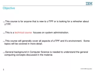
Objective • This course is for anyone that is new to z/TPF or is looking for a refresher about z/TPF. • This is a technical course focuses on system administration. • This course will generally cover all aspects of z/TPF and it’s environment. Some topics will be covered in more detail. • General background in Computer Science is needed to understand the general computing concepts discussed in the material. 1
Note on “CPU” terminology • TPF originated for single-CPU systems, some terminology has diverged from common IBM architecture terminology. • In z/Architecture terms, a “CPU” contains the sequencing and processing facilities for instruction execution, interruption action, and timing functions; and multiple CPUs in a system can run concurrently. • The TPF term for a z/Architecture CPU is an instruction stream, or I-stream. • In z/Architecture terms, a “system” includes main storage, one or more CPUs, the channel subsystem, and I/O devices. • TPF often refers to a z/Architecture system using the term CPU (confusing); each CPU is given a single alphanumeric character as an identifier called a CPU ID. (e.g. CPU 2) 2
Entry Control Block (ECB) • Entry • An entry is associated with an input message from an end user • An area of main storage is assigned to each entry for use as both an application work area and a system work area • This are of main storage is called an entry control block, or ECB • The ECB is the cornerstone of the application program re-entrant structure • Use of the ECB allows one program for multiple entries because each ECB is private to an entry (re-entrant code) • An “entry” is considered to be synonymous with an input message, • An end-user input message • A command from an operator • A time-initiated utility routine • A task “spun off” from another task to be executed asynchronously 3
Entry Control Block • Linked to a task (typically an input message ) • Maintains a record of resources used • Serves as the interface between the TPF system and the application, and other ECB-controlled programs. • Provides storage for system use AND application use • Each message executes code with an EC (# ECB's = multiprogram level) • One program can be used by many ECBs • re-entrant (cannot be self-modifying) • Entry unique data kept in ECB, code can be yes by multiple ECBs • The ECB model has characteristics of both a process and a thread • The footprint is lightweight like a thread • The ECB exhibits characteristics of a process • Each ECB has its own address space, stack area, heap storage, etc. 4
Entry Control Block • Within the ECB, there are work areas that are ordinarily an integral part of a non-reentrant program • EBW000-EBW103 is the primary work area of the ECB • Can be used to pass data from one program to another or as a scratchpad area for calculations • The following 8 bytes are typically inter-program bit switches • The inter-program switches are initialized to zero when the ECB is initialized • The secondary work area uses the same conventions • The ECB is allocated from main storage blocks • Portions of the ECB are defined as an application-programming interface (API) 5
ECB format • ECBs are allocated at IPL time. The number is user-defined . • The ECB is a 12K-byte block and is composed of 3 4K-byte pages • ECB page 1 • Used primarily by applications • Contains fixed application work areas • Defined and used by the application program and a fixed size. • Contains fixed system work areas, which are comprised of: • A interface area used by both the application program and the control program. This area contains the addresses of file records and working storage blocks the application program requested from the z/TPF system. • An entry-management area used by the control program. This area contains status information. • A user-definable area which can be used by application programs. 6
ECB format • ECB page 2 • Used primarily by the control program • Holds data related to system availability if damaged by the application program, e.g. control information used to manage the ECB and working storage blocks • Contains a pointer to the resource limit table (RLT), which contains two levels of limits for each resource that is monitored. • Contains a user-definable area • Uses a storage-access key of 2 for protection • The PSW key must be changed in order to update this area. • ECB page 3 • Used only by the z/TPF system control program • Contains data and tables related to the management and activity of the entry 7
Accessing and creating the ECB • The address of the ECB is in the ECB register, which is part of the interface when to the control program. • By convention of the z/TPF system, assembler programs address the ECB using register 9. C/C++ programs use the function ecbptr() to obtain the ECB address. • OPZERO (Operation program Zero) initializes the ECB register when the ECB is created. (the initial program) • OPZERO creates and initializes an ECB with data. • Where the input entry came ‘from’ • Where to send the response • The input message itself 8
Message Processing Overview • An input message causes an entry to be created • Application segments are dispatched for processing the input message. • The ECB makes requests of the control program for system services such as: • Input and output (I/O) • Storage allocation (both file and main storage) • Program fetches (called Enter/Back in the z/TPF system) • Release of control. • Many of the system services requested have other system services implied. e.g. if application ask to read a file record, and the record is not already in main storage, then the system must: • Obtain a working storage block in main storage for the record • Issue the I/O commands necessary to retrieve the record from file storage • schedule another entry (ECB) during the delay caused by the I/O. 9
CPU loop and shared ready lists • The z/TPF scheduler uses a system routine called the CPU loop to select an entry for execution • The CPU loop is also known as the system task dispatcher. • This routine sequentially interrogates system queues and clocks to determine what work the CPU will process next. • In a system with multiple I-streams, each I-stream has its own CPU loop. • The order of processing priority is the sequence in which the CPU loop interrogates queues. 10
CPU loop and shared ready lists • The CPU loop major lists, in processing priority, are: • Cross list, used for dispatching work between I-streams • Ready list, used to return control to an entry already created as the result of some completed system activity • Input list, used to dispatch a new entry for processing an input message • Deferred list, used to delay the execution of an entry • The cross list is I-stream-unique. (each I stream has one) If an I-stream wants to dispatch work on a different I-stream, the work item is placed on the target I-stream’s cross list. • The target I-stream removes the work item from the cross list and performs the associated task The ready list, input list, and deferred list have an I-stream-unique list and an I-stream-shared list; • Each I-stream checks its unique list first, followed by the shared list. 11
Processing the shared lists • The cross list and ALL shared lists must be locked when a shared list is modified. • Shared List Processing • If item has an I stream affinity, move it to a unique list • If item does not have an affinity, process it • Secondary (VCT and Suspend) List Processing • IS-unique Virtual File Access Count (VCT) list: VFA record access threshold exceeded • Every item from the VCT list will be processed (added to the IS-shared ready list) once every pass. • IS-unique Suspend list: LODIC/TMSLC processing • One item from the Suspend List will be processed after one pass through every item on the IS-shared input list. 12
List Processing Modifications • After an item is found on a list and then processed, • the scan of the lists is started over rather than resumed.(Dequeue) • The ZACLV command can be used to modify the processing of the lists. e.g. • The input list can be skipped after servicing it a certain number of times in order to ensure the deferred list is processed rather than “starved”. • The input list can be processed only when certain numbers of various blocks (e.g., ECBs, IOBs, etc.) are available. This prevents input messages, representing extra work, from being introduced into a system that is currently too busy i.e. not enough system blocks available to start additional work 13
ZSTAT – Display system status • Display status information about the z/TPF system, -the number of allocated and available main storage blocks - the number of active ECBs • Generate time-initiated displays of the status information. • Display information about I-stream utilization, - I-stream-unique work list counts, and - stream-shared work list counts. • Display information about the use of physical blocks based on owner name. • Display information about dumps. • Display information about the use of 31- and 64-bit system heap storage. • EXPLAIN THE IMPLICATIONS OF THIS DATA 14
ZSTAT Output - zstat CSMP0097I 11.06.44 CPU-B SS-BSS SSU-HPN IS-01 STAT0014I 11.06.44 SYSTEM STATUS DISPLAY _ IOB FRAME COMMON SWB ECB FRM1MB ALLOCATED 4096 5000 250 2048 300 300 AVAILABLE 4096 4991 248 1987 299 176 _ ACTIVE ECBS 1 DLY/DFR ECBS 0 PROCESSED 8 LOW SPEED 0 ROUTED 0 CREATED 281 SDO CREATED 0 SNA 0 THREADS CREATED 0 _ TCP/IP INPUT 0 TCP/IP OUTPUT 0 END OF DISPLAY+ 15
Message flow • The system is initialized and the CPU loop is in control. • CPU loop keeps looping and checking for work on the cross, ready, and input lists. IN THAT ORDER. • The CPU loop handles input messages (MSGS USALLY BLOCKED TOGETHER FROM CCU) Messages arrive from actions initiated by the: >CPU loop invokes the communications control input routine which starts an I/O operation to read the data from the communication network >I/O interrupt handler. . • The CPU loop finds an item on the input list. OPZERO gets and initializes an ECB,... COMM SOURCE then invokes the application. 16
Message flow through z/TPF • Fetch the application program from disk using I/O.(if necessary) • The program segment is read into main storage and the program is started. • Running applications. An ECB obtains a block of main storage in which the output message is built. • Sending the reply. When processing of the input message is complete, the output message is transmitted to the end user over communication facilities. • Release resources and clean up. When all the processing required by an entry is complete, an EXITC macro is issued. All main storage utilized for processing the input message is released. 17
Entry termination (EXIT processing) • An exit macro request (EXITC) is used to end processing an ECB in the z/TPF system. • System resources held by the exiting ECB are returned to the system • Control is transferred to the exit program either because an exit macro was issued or because of the occurrence of a system error. • The exit program accomplishes the following: • Disconnects from the ECB all programs associated with the ECB. • Releases all main storage blocks, used by the ECB. Releases all data records held by the ECB. • Closes any tapes or unit record devices opened and assigned to the ECB • Ensures that all I/O initiated is completed • Releases the ECB. 18
Main storage management – Virtual address space • Virtual Storage • Uses Dynamic Address Translation (a hardware feature) to translate a virtual address to a real address. DAT indicator is bit 5 in the PSW. • Protects real storage from being corrupted. • The z/TPF system defines types of virtual address spaces, which are mappings of main storage. • The system virtual memory (SVM) mapping is all of main storage. • The ECB virtual memory (EVM) mapping is all of main storage that can be used (addressed) by an entry. • An application program (ECB-controlled program) uses the EVM mapping of main storage when processing. • The control program uses both the SVM and EVM mappings of main storage depending on the type of service it provides at any given time. 20
Main, fixed, and working storage • Main storage • Consists of fixed storage and working storage. >Fixed storage Areas of main storage whose sizes are determined at system generation (i.e., system data records and tables). Fixed storage is permanently allocated by the control program. >Working storage = Main Storage minus fixed storage Areas of main storage that are: • Available to application programs as system resources • The system control blocks used for managing an entry. -The amount of working storage available to application programs depends on the number of system control blocks, common blocks, and other system resources in use at any given time. 23
Working storage • Working storage is divided into distinct block types: • 1M-byte frames • I/O blocks (IOBs) • System work blocks (SWBs) • Entry control blocks (ECBs) • 4K-byte frames • 4K-byte common blocks. • These block types are physical storage blocks • defined by owner information • a 32-byte descriptor, divided into three sections, that is saved in the associated control table entry for the storage block. • An owner could be application like ‘end transaction’ or more system oriented like ‘tape’ • Most macros that get storage by using physical blocks (such as GETBC, GSWBC, GCOMC, etc.) have an OWNER parameter. The owner name for an ECB is set by using the EOWNRC macro or the tpf_eownrc C function. 24
1M-byte frames and 4K-byte frames • 1M-byte frames • A 1M-byte frame is a block of virtual storage which is backed up by real storage. --The 1M-byte frame control table (MFCT) manages all in-use and available 1M-byte frames. --There is no direct application interface. --Used for ECB-heap and application-stack storage when the pre-allocated areas are depleted. --It is also used for 64-bit ECB heap requests. • 4K-byte frames • Used by the control program to satisfy requests from ECB-controlled programs for storage in a standard block size (128, 381, 1055, or 4K). • CP manages the allocation of these frames. • A 4K frame is a block of virtual storage; logical storage blocks are allocated to an ECB from this physical block and are private to an ECB. • A 4K common frame is a block of virtual storage. • When an entry requests a common block, it is allocated from this physical block regardless of its size. 25
4K-byte common frames • A 4K common frame is a block of virtual storage. • When an entry requests a common block, it is allocated from this physical block regardless of its size. • Common blocks are available in standard block sizes. • The virtual addresses of common blocks are mapped in each ECB’s address space and backed by the same real address range. ( V = R) • An ECB can “see” all common blocks just like all other common blocks. As a result, common blocks are a form of shared storage. • Common blocks are typically a limited resource and should be used with discretion. • They are a “free fire zone” 26
Logical storage blocks • Logical Storage Blocks • Used for data records, message blocks, keypoint records, and program segments. • These blocks can be private to an ECB or shared between ECBs depending on whether they are allocated from a 4K frame or from a 4K common frame. • When logical storage blocks are located in an area private to the ECB (a 4K frame) they are private logical blocks or just logical blocks. • When logical storage blocks are located in 4K common frames, they are referred to as common blocks and can be used to pass information among ECBs. • The relationship of a frame to (private) logical blocks is: • One 4K frame = one 4KB logical block • The relationship of a common frame to common blocks is: • One 4K common frame = one 4KB common block 27
Logical storage blocks • An application program requests a logical storage block, the control program puts the block address into one of the 16 slots in the ECB ( core block reference words -CBRWs). • Each CBRW is associated with a data level identified in macros as Dn (for data level n) where n is a hexadecimal number between X'0' and X'F'. For example, D3 is known as data level three. 28
Data event control block (DECB) overview • Before DECB support, the z/TPF system only 16 data levels were allowed (D0-DF) • A DECB can be used in place of data levels for FIND/FILE-type I/O requests. (see next foil) • Although a DECB does not physically reside inside an ECB, it contains the same information as standard data levels: • Core Block Reference Word (CBRW) • File Address Reference Word (FARW) • File Address Extension Words (FAXWs) • Detailed error indicator. 29
ECB resource monitor (ecbRM) • The ECB resource monitor provides a centralized facility that monitors the use of selected system resources for each ECB. • The ECB resource monitor detects and, optionally, stops an ECB that requests excessive amounts of monitored resources. • Enables the customer to monitor the use of system resources before the system has a problem, • Provides operational control and flexibility- the ZECBM command to turn the ECB resource monitor on or off. • The ecbRM detects and terminates any ECB requesting excessive quantities of monitored resources. • Two levels of resource limits exist for each monitored resource. • ecbRM may be controlled by the operator or by a program. • There are ecbRM related User Exits to modify what and how monitoring is done. 31
ECB private area (EPA) • The get core macro (GETCC) dispenses a logical storage block in a standard size (128, 381, 1055, or 4K). When the entry requests a (private) logical block, it is dispensed from the ECB private area, when the entry requests a common block, it is dispensed from a 4K common frame. The size of the ECB private area is defined with the CORREQ macro during SIP processing (system generation) • The ECB private area (EPA) is private to an entry, it’s not accessible by other entries. • Regardless of its actual location in main storage, an entry views its EPA as if it is located below the 2-GB bar. (31 bit addressing) (V != R) 32
ECB heap, application stack, and system heap • ECB heap • Applications can request contiguous storage from the ECB heap . ECB heap storage is private to the ECB. • Application stack • Application stack storage is acquired by z/TPF and is private to the ECB. This is a work area for things like register save areas, etc., for C and assembler programs. • System heap • The GSYSC macro obtains a variable-sized contiguous storage area from a system heap area. The System heap is not private to the ECB. System heap is requested in 4-KB or 1-MB units. • ECB heap storage (system heap storage) is not returned to the system when the ECB exits. System heap storage is persistent across ECBs but temporary from the system point of view in that it can be released by the RSYSCmacro 33
31-bit and 64-bit system heap • 31-bit System heap • Located below the 2-GB bar. A minimum size is defined for 31-bit system heap storage. z/TPF might allocate more than the minimum size, depending on where the 4-KB frames end in the SVM or where the 31-bit ECB heap ends in the EVM, whichever is greater. • This is up to the next 1-MB boundary and from that point to the 2-GB bar is the size of the 31-bit system heap. All virtual addresses in this area are backed using 1-MB frames • 64-bit System heap • Located above the 2-GB bar. The size of the 64-bit system heap is determined by the total size of 1-MB frame storage. • The starting virtual address is on a 2-GB boundary. Applications can request contiguous storage from the ECB heap ECB heap storage is private to the ECB. 34
Copy-On-Write facility • Some programs may require special processing for the data in storage • Programs that update static data • Programs that have global constructors • These programs are placed in the copy-on-write core-resident-program area (CRPA). • When the z/TPF system fetches this type of program, the program is page-protected in the ECB virtual memory (EVM) address space for all ECBs to avoid accidental corruption. • If a program attempts to update static data, the Copy on Write process occurs • For global constructors, the indicator that the constructor has not been run is in page-protected storage. A new private copy of the page is made, and the private copy is updated to indicate the constructor has been run. 35
Memory configurations • Memory configurations allow a z/TPF image to run on systems with different amounts of memory. • Other non-memory system settings don’t have to be duplicated • Allows the same system definition to be used on a production system with large amounts of memory, and on a test system with much smaller amounts of memory • A memory configuration defines the allocation of core resourcessuch as IOBs, SWBs, and frames. Memory allocations are defined in key-point A • As many as eight memory configurations are available to be used. • When the z/TPF system is IPLed, the control program matches a memory configuration to a physical processor by best fit. • It uses the memory configuration that requires the most amount of storage after meeting the requirements of a minimum amount of both VFA and the 31-bit system heap. • The ZCTKA PREFER command can specify that a certain memory configuration is preferred so that the system will try to use this configuration first. 36
Program linkage – Enter/Back • z/TPF programs are invoked through one of the create macros or the following er macros: • ENTNC -- Enter with no return. The calling program does not expect a return of control. • ENTRC -- Enter with return. The calling program expects to get control back. When a BACKC macro is encountered during entry processing, BACKC returns control to the last program that issued an ENTRC. • ENTDC -- Enter and drop previous programs. An ECB-controlled program is called and the Enter-Back macro control information that was saved is reinitialized to remove linkages to all previous programs. • SWISC TYPE=ENTER -- Transfer the ECB to another I-stream and drop previous programs. This macro performs the function of ENTDC while transferring the ECB to another I-stream. 37
File storage (DASD) access • Although several different file storage devices (DASD), , all file accessing is conceptually done in a similar fashion. • The generic terms used for file accessing areFind (read a record) and File (write a record). WAITC is an important macro used with I/O operations. WAITC is an application program request to delay further processing until all the pending I/O operations for the application program issuing the WAITC are completed. An I/O counter within the ECB is used for this control. • A level is one of the 16 pairs of data fields in the ECB: • File address reference word (FARW) • Core block reference word (CBRW). 38
File storage (DASD) access • The file address reference word (FARW) is used to identify a file address (record) between the application and the control program. • The core block reference word (CBRW) is used to pass an address of a main storage block used for storing data. A main storage block obtained by the control program for a find macro.. • The allocation of data to physical file storage and the use of find and file macros are important: • The record sizes used with find and file macros correspond to the same sizes used by the main storageallocation functions. • Predefined records, are managed in a file area known as fixed-file records. A set of data within the fixed file area is identified as a record type. Within a fixed-record type each record is identified with an ordinal number. • The dynamic requirements for file storage are satisfied by areas known as pools. The allocation of the pool record area to physical devices is also done during system generation. However, the pool record area represents a large repository of file storage accessible by all applications. 39
File storage (DASD) access • The z/TPF system determines the physical location of data, that is, the addresses used by the hardware. This is done in stages: • An application request to find or file a record must be preceded by either: • Use of the get file storage macro to obtain a pool record. • Use of a system program to obtain the FARW of a fixed record, given the record type and ordinal number. • An application program, in turn, passes a file address reference to I/O service routines through the use of FIND and FILE macros and the FARW of the ECB. • The file address information is in a format of either pool or fixed data record references by the time a find or file macro request is issued. The use of data within fixed records as indexes to pool records is a common technique used in the z/TPF system environment. i.e. Fixed records refer to Pool records 40
Virtual File Access - VFA • Conceptually similar to the virtual storage page pools used in other virtual storage operating systems • Provides an intermediate staging area between the application program data and the DASD file storage • Most filed records are copied into VFA; how they are written to DASD is based on their handled whether or not they are immediately copied to DASD • Because the VFA area is in real main storage, much higher access rates can be achieved and input/output (I/O) channel load reduced. • Because the number of records competing for residency in VFA storage exceeds the size of VFA, only the most active records will be readily accessible - to reduce competition, some selectivity is allowed in the number and type of records that can become resident in VFA , • To further relieve I/O channel load, VFA permits multiple updates to be applied to a record resident in VFA without the updates being reflected to the database copy until necessary.... System failure? 41
VFA • Storage allocated for VFA is typically very large • After all other storage is allocated, the remaining unallocated storage is used for VFA...Can be several gigabytes or more • VFA routines use two chains: • Aging chain • Holds most of the records in VFA • Holds current VFA records that may have a delayed file pending • Reserve chain • Holds records that can be overlaid with a new VFA candidate because they were not referenced a minimum number of times and the records do not have a delay file pending...can be kicked out • Any record on the reserve chain can still be referenced by an application find...rescued from the chain? 42
VFA • The VFA reserve chain contains a minimum percentage of VFA records If the number drops below a user-specified threshold then algorithms move records from the aging chain to the reserve chain • The size of the reserve chain should be large enough so that when a delay file buffer is moved from the aging chain to the reserve chain and the write is scheduled, - the write is completed by the time an attempt is made to allocate the buffer for a new record I.e the write finishes before the buffer is reallocated. 43
VFA candidacy • Records are identified as VFA candidates in the record ID attribute table (RIAT) Use the ZRTDM command to define or display records as VFA candidates Record IDs can be defined with the following attributes: • Delay filing – When a file is requested, the record is copied to VFA but not filed physically to DASD. The record is filed later, asynchronous VFA storage management or during cycle-down. • Synchronized delay filing – Similar to delay filing except the record is filed when another processor requests the record. This maintains database consistency if multiple processors update the record. • Immediate filing – The record is physically filed to DASD. However, there is no synchronization between processors: a record filed by one processor is not updated in the VFA of another processor. • Synchronized immediate filing – Similar to immediate filing except changes are kept synchronized between loosely-coupled processors. 44
VFA locking • The RIAT attributes also allow you to specify two types of record locking: • DASD locking Records that are to be held for exclusive use are fetched from DASD so that the external lock facility (XLF) can be used to grant exclusive use to one processor. • Processor locking • A read-only or processor-unique record bypasses the XLF when the record is located in VFA. The VFA copy is fetched and no DASD I/O is performed. • Do not use this option unless extremely high performance is required. Because the XLF is bypassed, the data integrity of the record can be compromised. 45
TPF images • An image is a set of programs and data that primarily includes: • IPL areas (IPLA and IPLB) • Core-image-restart (CIMR) area components • Control program (CP) • In-core dump formatter (ICDF) program • Online component of the general file loader (ACPL) • Global synchronization table (SIGT) • Record ID attribute table (RIAT) • File address compute program table (FCTB) • USR1 &USR2 • E-type programs and program-attribute table (PAT) • Keypoints • Multiple images can share IPL areas and E-type program areas • The CIMR components of one image can be copied to a new image • This copy can be either logical or physical 46
Image IPL • Primary image • One image is defined as Primary • IPL area of the primary image is used during a “hard” IPL • In IPLB, the operator is prompted to select an image • If the selected image’s IPL area is different from the primary image’s IPL area then the new IPLA is loaded and a re-IPL is performed • The re-IPL is a software IPL • TPF commands allow you to redefine the contents of each image, change the primary image, and enable and disable an image • An image must be disabled in order to modify its contents • An image must be enabled in order to use it as part of system IPL • New code can be loaded to an image and then IPLed in order to begin using the new code • If a problem is found with the code, the system can be re-IPLed using the previous image or another fallback image 47
Loadsets • A loadset is a group of E-type programs identified by a unique name on which E-type loader functions can be performed. • Loadsets are similar to images • Like images, loadset are often used to test programs. • Like images, loadsets can be enabled and disabled • Unlike images, loadsets can be loaded to the z/TPF system and made active without requiring an IPL. • E-type programs can be loaded as part of an image or as part of a loadset • If a set of programs to be tested includes only E-type programs then a loadset provides more flexibility than an image 48
Using a loadset • The z/TPF build-environment tools are maketpf, loadtpf, bldtpf, etc. • These tools can assemble/compile programs, create loadsets, and FTP the loadsets to a z/TPF system • More information on these commands is provided in another presentation • Once the loadset is , in the TPF file system, use the ZOLDR LOAD command to load the loadset into the system. • In order to begin using the programs in the loadset, use the ZOLDR ACTIVATE command to activate the loadset and begin testing the programs. This makes the new programs available. • If changes are required to the programs in a loadset, use the ZOLDR DEACTIVATE command to deactivate the loadset and resume using the previous versions of the programs. • Once testing is complete, use the ZOLDR ACCEPT command to replace the base versions of the programs with the new versions. 49
Other commands for use with loadsetsSKIP THIS FOIL • ZOLDR CLEAR – clear and initialize all E-type loader file-resident records the first time the system is IPLed or if E-type loader records are damaged. • ZOLDR ACTIVATE with SEL option – Selectively activate a loadset to limit the use of new programs to specific terminals, lines, users, etc. • ZOLDR DELETE – delete a deactivated loadset; causes all of the fixed file records associated with a loadset to be returned to the pool of available fixed file records. It also removes the z/TPF collection support file system (TFS) files associated with a loadset. • ZOLDR EXCLUDE – exclude a program from an existing loadset. If the loadset is active, ZOLDR EXCLUDE deactivates the program on all processors. An excluded program will not be included in later functions performed on the loadset. For example, if you exclude the PGM1 program from the GROUP1 loadset, PGM1 is not activated when you activate GROUP1. • ZOLDR REINCLUDE – undo a ZOLDR EXCLUDE. • ZOLDR ALTER PROGCHAR – change the characteristics of unallocated E-type programs, such as NOKEY0, NOMONTC, NORESTRICT, and NOCMB 50