Download
1 / 38
380 likes | 510 Views
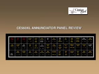
This document outlines critical operational indicators for inverters, including primary, secondary, and auxiliary units. It details how these indicators reflect the operational status and potential failures of power buses, emphasizing the management of fixed frequency busses. Key alerts involve losses of power due to AC transformer issues, TRU failures, and overheating conditions in various systems. The operation of circuit breakers, temperature thresholds, and system tests is also explored, ensuring proper functionality and safety measures are in place for aircraft electrical systems.

E N D
Indicates primary inverter is inop. Operational secondary and auxiliary inverters will Maintain power to all fixed frequency busses.
Indicates secondary inverter is inoperative. Operational primary and auxiliary Inverters will maintain power to all fixed frequency buses.
Indicates auxiliary inverter is inoperative. Operational primary and secondary Inverters will maintain power to all fixed frequency buses.
Indicates no power to applicable bus. This is due either to a failure of the 26 volt AC Transformer (26 volt AC services lost), or loss of power at the 115 volt AC fixed Frequency bus ( both 115 volt AC and 26 volt AC services lost.)
Illuminates to indicate horn heater elements are unpowered or failed while system is Activated by a HEAT selection. During test selection light illuminates for 2 Sec. then Goes out to verify system function.
GCU has isolated faulty bus due to generator malfunction or bus fault. Will also get A TRU fail light, PISSWATER gone.
Indicates applicable TRU is off-line or failed. Secondary bus on the failed side will be Cross tied to the remaining TRU output by logic relays. A single TRU is sufficient to Operate all secondary DC services. A double TRU failure will cause the logic relays to Tie the secondary buses to the main feeder busses. This allows the 28 volt DC Generators to provide power for secondary DC services.
Illuminated – Flight compartment EMER LIGHTS switch selected off while electrical Power is applied to the airplane. Light extinguishes when EMER LIGHTS switch Is selected to ARM or ON.
Illuminate to indicate related pitot head heater is deenergized, either by OFF selection Or power failure.
Illuminate to indicate an overheat condition of the associated windsheild, or side Window, or temperature controller or temp. sensor malfunction. For a windshield Overheat condition, power is automatically cut off from the heater elements (light Comes on) until the HEAT switch is selected to WARM UP (light goes out). After Appropriate cooling the switch may be selected to NORM. For a side window overheat condition, the FLT WDO/HT switch is selected to OFF. The caution light should go out as window cools off if the caution light remains Illuminated the FLT WDO/HT circuit breaker should be pulled.
Indicates overheat of applicable TRU. Select TRU off by pulling L TRU or R TRU Circuit breaker located on variable frequency AC breaker panel.
Indicates applicable hydraulic system fluid has exceeded a temperature of 109 C As sensed at the reservoir. The caution light will extinguish if fluid cools to 95 c.
Illuminates to indicate overheat (over 88c) in flight compartment supply duct. Temperature trim valves are driven to maximum flight compartment cooling Position. When temperature drops below 82c, normal operation resumes and caution Light goes out. Illuminates to indicate overheat (over 88c) in cabin supply duct. Pack temperature Control valves are driven to maximum cooling position. When temperature drops below 82c, normal operation resumes and caution light goes out.
Indicates that the electric motor windings driving the applicable standby pump has a Temperature exceeding 170c. The caution light will extinguish if motor cools to 160c.
Indicates that applicable battery not connected to its main feeder bus. Normal Indication when battery is selected off.
Illuminates when system pressure falls below 5.5 psi as sensed at passenger door Supply line.
Illuminates when the air temperature downstream of the pressure regulator and Shutoff valve (PSRV) in the bleed air supply duct exceeds 290 c. The affected PSRV And high pressure bleed valve close to cut off hot air supply to the duct. Bleed air Supply for the de-icing system will be unaffected. When duct temperature drops below 290c the light will extinguish and bleed air operation in the affected nacelle will be Restored.
Indicates overheat of applicable DC generator. Select generator off until light Extinguishes.
Indicates overheat of applicable AC generator. Select generator off until light Extinguishes.
Illuminate to indicate affected engine ECU fuel scheduling is cancelled and engine Is operating on Manual HMU fuel schedule.
Fuel boost pressure to engine inlet inadequete (less than 5.5 psi) / Boos ejector Pump failed.
Affected system hydraulic pressure has dropped below 2000 psi. Will illuminate with A pump failure, hydraulic fluid loss, or engine shutdown/failure.
Indicates applicable 28 volt DC generator is off line or shut down by the GCU due to Generator malfunction or bus fault. Main feeder bus on the failed side will be cross Tied to the remaining generator output if indicated generator is off line due to Reasons other than bus fault. A double generator failure will cause the logic relays To tie the main feeder buses to the secondary buses. This allows the TRU’s to Maintain power to the main and essential busses.
Indicates applicable AC variable generator is off line or shut down by the GCU due to Generator malfunction. Variable frequency buses on the failed side will be cross tied To the remaining generator output.
Indicates that the isolation valve on the affected hydraulic system has closed. This Valve isolates the affected hydraulic system’s rudder actuator from the remainder of The hydraulic system. This valve will close when there is a drop in system fluid level Due to fluid loss (approx. 2/3 fluid left). The rudder actuator on the affected system Will be able to continue to operate using fluid which is circulated in a closed system Loop.
Fuel tank quantity in collector tank falls below 130 pounds.
Indicates rudder actuator pressures have either not dropped to 900 psi when Airspedd exceeds 140 kts. IAS or risen to 1500 psi when airspeed drops below 140 Kts. IAS. There is a 200 kt. IAS limitation associated with whis light. Usually illuminates in conjunction with #1 RUD HYD or #2 RUD HYD caution lights. Indicates that a rudder actuator has depressurized and the remaining actuator is Receiving full system pressure (3000 P.S.I.) There is a 200 Kt. IAS limitation associated With this light.
Indicates that one of the inboard or outboard spoiler lift/dump valves is not Positioned correctly. The affected spoiler system may not extend upon aircraft Touchdown. Indicates no metered extend pressure to affected spoiler system actuators. Applicable ROLL SPOILER PRESSURE push off light in front of F/O should be pushed to Deactivate the malfunctioning system.
Indicates that the applicable rudder actuator is depressurized or that pressure has Fallen below 600 P.S.I. There is a 200 Kt. Limitation associated with these lights.
When illuminated this light indicates that the secondary shafting of the flap system is Experiencing torque loading associated with the extension or retraction of flaps. Indicates possible failure of primary flap drive shafting. Hydraulic pressure to the flap drive system has fallen below 1500 P.S.I. Possibility of Flaps being immobilized in their existing position.
Stall transducer or lift computer on affected side has failed or the system is Deenergized. Nose wheel steering ECU failure/ Nose wheel in free castor mode.
Anti skid system is unserviceable or system is selected off / Lights illuminate Briefly during test. After retraction indicates gear door sequence valve failure. Landing gear must not be Extended by normal DN selection. Use alternate handpump when gear extension is Required.
Illuminates with beacon light selected off. Parking brake set.
Indicates failure in a w.o.w sensor. PSEU will continue to provide WOW signals due to circuit and sensor redundancy. Refuel / Defuel selection made on refuel / defuel control panel Master caution light is not activated when illuminated Fuel transfer not possible.
Fire in baggage or cargo compartment / smoke detector self test. Illuminates concurrent with both alarm and Fault conditions. Cabin altitude exceeds 10,000 ft. Oil pressure drops below 40 P.S.I. shutdown engine.
Door opened Temperature of applicable battery has exceeded 65 c battery should be disconnected From DC electrical system and closely monitored.