Download
1 / 19
190 likes | 316 Views
This presentation by Rene Messier from Data Translation explores the differences between multiplexed and simultaneous data acquisition architectures. It discusses key criteria such as resolution, channels, speed, and range. While multiplexed systems utilize a single A/D converter requiring sequential channel sampling, simultaneous systems provide distinct converters for each channel, eliminating time skew and enhancing accuracy. The session highlights performance metrics, settling times, source impedance impacts, and application use cases for simultaneous devices. Discover how simultaneous data acquisition offers higher precision and efficiency for various industries.

E N D
Multiplexed vs. Simultaneous Data Acquisition Using USB Devices Presented by: Rene Messier Company: Data Translation
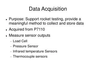
DAQ Criteria • Resolution • Number of Channels • Speed • Range In addition, the particular analog input architecture chosen will affect the sampling and accuracy of your results.
Architectures Multiplexed Simultaneous • Multiplexed systems use one A/D converter • Simultaneous systems use an individual A/D converter for each channel
Channel to Channel Skew Eliminated • Simultaneous Sampling • Eliminates time skew between channels • Simplifies both time and frequency based analysis techniques • Multiplexed Sampling • Channels are sampled sequentially • May require software correction for detecting certain patterns
Multiplexed Architecture One A/D Converter An Instrumentation Amp A Multiplexer Performance: CH Rate per channel Signal Bandwidth 150kHz 75kHz 75kHz 37.5kHz 50kHz 25kHz 37.5kHz 18.75kHz 30kHz 15kHz 25kHz 12.5kHz Simultaneous Architecture A/D Converter per chan A Track-Hold per chan No Multiplexer Performance: CH Rate per channel Signal Bandwidth 150kHz 75kHz 150kHz 75kHz 150kHz 75kHz 150kHz 75kHz 150kHz 75kHz 150kHz 75kHz Increased Signal Bandwidth
Higher Signal Bandwidth • Bandwidth is the area of all frequencies up to the 70% roll-off point • Data Translation products offer a front end bandwidth that is ten times the Nyquist Limit • Minimizes roll-off and phase errors
Built In Accuracy • Simultaneous A/D Converters • All inputs sampled at same time • Single clock pulse to acquire all channels • 35nS max aperture delay • Matched within 5nS across all circuits • 1nS jitter (aperture uncertainty) • Higher Accuracy at High Speed • Eliminate several sources of error • Settling Time • Channel-to-channel crosstalk
Settling Time For Mux’d Systems • Each Channel is tied to the same A/D • Minimum settling time is required for the switched voltage to reach the actual input signal level • Some portion of signal from previous channel can “cross over” to next channel • Makes source impedance an issue • Can generate erroneous results
Source Impedance and Settling Time • Source Impedance (R) • Capacitance (C) • R * C = 1 Time Constant • 9 TC’s typical to settle within 0.01% accuracy Assume: 10V on Channel 0 0V on Channel 1 (R = 10kOhm) C = 100pF 1TC = (10kOhm * 100pF) = 1uS 0.01% accuracy requires 9 TC’s 9 * 1uS = 9uS (~110kHz)
Channel-to-Channel Crosstalk • Signal on a channel couples with the signal on another channel • Occurs because of parasitic capacitance across each open switch Example: • Assume an 8 channel MUX’d system: • Each 5pF capacitor can cause crosstalk between channels • (5pF * 7ch) = 35pF
Adding OP Amps to Your Signal Conditioning • MUX’d System • Slow-speed OP Amp • Long Settling Times • Errors in Measurement (described previously) • Added Cost • High-speed OP Amp • Will Ring When Hit with the 100pF Switch Transients From the MUX • Added Cost • Simultaneous System • No MUX, No Settling • No added cost
How Precise is Your Simultaneous Acquisition Device? • Measured in Aperture Jitter (Uncertainty) • How to Measure Aperture Jitter: • Input a full scale sinusoidal signal on all channels • Find the voltage change near the zero-crossing • Compare voltage change to A/D resolution Demonstration…
1) A sinusoid is determined by the equation: V(t) = pSin(2πft) where: p = peak voltage of sine wave f = frequency of sine wave V = voltage t = time (in seconds) 2) In order to find the voltage change near the zero-crossing, take the derivative: (6.283 * 10,000Hz * 10V) = 628,300 dV / dt (ΔV in 1 second) (628,000 * .000000001) = 628uV (ΔV in 1 nanosecond)
3) Compare voltage change to A/D resolution: ΔV = 628uV in 1nanosecond Given a 16bit A/D the resolution is: (20V / 65536) = 305uV So, with an aperture uncertainty of 1nS, a 10kHz signal should yield a voltage change near the origin of 628uV or ~2 bits of error for a 16-bit A/D converter.
Cost vs. Value For many applications, a simultaneous acquisition device is certainly the architecture of choice due to its inherent speed and accuracy but, until recently, the cost of these devices was somewhat prohibitive. Times have changed and simultaneous devices are now as cost effective as multiplexed devices. Data Translation has designed a series of simultaneous data acquisition modules for USB 2.0. The Simultaneous Series provide high speed, highly accurate measurements, useful in many applications. • Semiconductor device testing • Nanotechnology testing • Motion Control • Industrial Applications • Automotive testing
Exceptional Quality and Value • DT9836 • Features • Simultaneous Sampling • High 225kHz per Channel throughput • 6 or 12 channel versions • 0 or 2 channel D/A output • 32 Digital IO bits • 5 Counter / Timers • 3 Quad Decoders • Competitive pricing