Object-Oriented Software Design (lecture 7)
Explore key concepts like Objects, Classes, Inheritance, Abstraction, Encapsulation, Polymorphism, and more for efficient software design. Understand the advantages of OOD, UML modeling, and the importance of different UML diagrams.

Object-Oriented Software Design (lecture 7)
E N D
Presentation Transcript
Object-oriented Concepts • Basic Mechanisms: • Objects: • A real-world entity. • A system is designed as a set of interacting objects. • Consists of data (attributes) and functions (methods) that operate on data • Hides organization of internal information (Data abstraction) • Examples: an employee, a book etc.
m8 m7 mi are methods of the object m1 Data m6 m2 m5 Object m3 m4 Model of an object Object-oriented Concepts
Object-oriented Concepts • Class: • Instances are objects • Template for object creation • Examples: set of all employees, different types of book
Object-oriented Concepts • Methods and message: • Operations supported by an object • Means for manipulating the data of other objects • Invoked by sending message • Examples: calculate_salary, issue-book, member_details, etc.
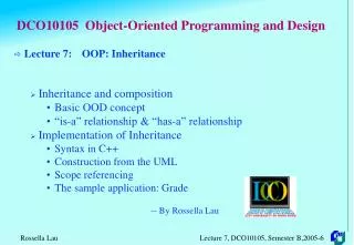
Object-oriented Concepts • Inheritance: • Allows to define a new class (derived class) by extending or modifying existing class (base class) • Represents Generalization-specialization relationship • Allows redefinition of the existing methods (method overriding)
Object-oriented Concepts • Multiple Inheritance: • Subclass can inherit attributes and methods from more than one base class • Multiple inheritance is represented by arrows drawn from the subclass to each of the base classes
LibraryMember Base Class LibraryMember Base Class Faculty Students Staff Derived Classes Faculty Students Staff Multiple Inheritance UnderGrad PostGrad Research UnderGrad PostGrad Research Object-oriented Concepts
Object-oriented Concepts • Key Concepts: • Abstraction: • Consider aspects relevant for certain purpose • Suppress non-relevant aspects • Supported at two levels i.e. class level where base class is an abstraction & object level where object is a data abstraction entity
Object-oriented Concepts • Advantages of abstraction: • Reduces complexity of software • Increases software productivity • It is shown that software productivity is inversely proportional to software complexity
Object-oriented Concepts • Encapsulation: • Objects communicate outside world through messages • Objects data encapsulated within its methods
Methods m4 m3 Data m5 m2 m6 m1 Concept of encapsulation Object-oriented Concepts
Object-oriented Concepts • Polymorphism: • Denotes to poly (many) morphism (forms) • Same message result in different actions by different objects (static binding)
Object-oriented Concepts • Dynamic binding: • In inheritance hierarchy, an object can be assigned to another object of its ancestor class • A method call to an ancestor object would result in the invocation of appropriate method of object of the derived class
Object-oriented Concepts • Dynamic binding: • Exact method cannot be known at compile time • Dynamically decided at runtime
Object-oriented Concepts • Composite objects: • Object containing other objects
Advantages of Object-oriented design • Code and design reuse • Increased productivity • Ease of testing & maintenance • Better understandability • Its agreed that increased productivity is chief advantage
Advantages of Object-oriented design • Initially incur higher costs, but after completion of some projects reduction in cost become possible • Well-established OO methodology and environment can be managed with 20-50% of traditional cost of development
Object modelling using UML • UML is a modelling language • Not a system design or development methodology • Used to document object-oriented analysis and design • Independent of any specific design methodology
UML • Based Principally on • OMT [Rumbaugh 1991] • Booch’s methodology[Booch 1991] • OOSE [Jacobson 1992] • Odell’smethodology[Odell 1992] • Shlaer and Mellor [Shlaer 1992]
OMT UML Booch Methodology OOSE Different object modelling techniques in UML UML
Why UML is required? • Model is required to capture only important aspects • UML a graphical modelling tool, easy to understand and construct • Helps in managing complexity
UML diagrams • Nine diagrams to capture different views of a system • Provide different perspectives of the software system • Diagrams can be refined to get the actual implementation of the system
UML diagrams • Views of a system • User’s view • Structural view • Behavioral view • Implementation view • Environmental view
Behavioural View • Sequence Diagram • Collaboration Diagram • - State-chart Diagram • - Activity Diagram • Structural View • Class Diagram • Object Diagram • User’s View • Use Case • Diagram • Environmental View • Deployment Diagram • Implementation View • Component Diagram Diagrams and views in UML UML diagrams
Are all views required? • NO • Use case model, class diagram and one of the interaction diagram for a simple system • State chart diagram in case of many state changes • Deployment diagram in case of large number of hardware components
Use Case model • Consists of set of “use cases” • An important analysis and design artifact • Other models must confirm to this model • Not really an object-oriented model • Represents a functional or process model
Use Cases • Different ways in which system can be used by the users • Corresponds to the high-level requirements • Represents transaction between the user and the system • Define behavior without revealing internal structure of system • Set of related scenarios tied together by a common goal
Use Cases • Normally, use cases are independent of each other • Implicit dependencies may exist • Example: In Library Automation System, renew-book & reserve-book are independent use cases. But in actual implementation of renew-book, a check is made to see if any book has been reserved using reserve-book
Example of Use Cases • For library information system • issue-book • Query-book • Return-book • Create-member • Add-book, etc.
Representation of Use Cases • Represented by use case diagram • Use case is represented by ellipse • System boundary is represented by rectangle • Users are represented by stick person icon (actor) • Communication relationship between actor and use case by line • External system by stereotype
Tic-tac-toe game Play Move Player Use case model Example ofUse Cases
Why develop Use Case diagram? • Serves as requirements specification • Users identification helps in implementing security mechanism through login system • Another use in preparing the documents (e.g. user’s manual)
Factoring Use Cases • Complex use cases need to be factored into simpler use cases • Represent common behavior across different use cases • Three ways of factoring • Generalization • Includes • Extends
Pay membership fee Pay through credit card Pay through library pay card Use case generalization Factoring UsingGeneralization
Base use case Common use case <<include>> Use case inclusion Base use case Base use case <<include>> <<include>> <<include>> <<include>> Base use case Base use case Base use case Paralleling model Factoring Using Includes
Base use case Common use case <<extends>> Use case extension Factoring UsingExtends
Class diagram • Describes static structure of a system • Main constituents are classes and their relationships: • Generalization • Aggregation • Association • Various kinds of dependencies
Class diagram • Entities with common features, i.e. attributes and operations • Classes are represented as solid outline rectangle with compartments • Compartments for name, attributes & operations • Attribute and operation compartment are optional for reuse purpose
LibraryMember Member Name Membership Number Address Phone Number E-Mail Address Membership Admission Date Membership Expiry Date Books Issued issueBook( ); findPendingBooks( ); findOverdueBooks( ); returnBook( ); findMembershipDetails( ); Example ofClass diagram LibraryMember LibraryMember Member Name Membership Number Address Phone Number E-Mail Address Membership Admission Date Membership Expiry Date Books Issued Different representations of the LibraryMember class
* 1 borrowed by Library Member Book Association between two classes Association Relationship
Aggregation Relationship • Represent a whole-part relationship • Represented by diamond symbol at the composite end • Cannot be reflexive(i.e. recursive) • Not symmetric • It can be transitive
1 * 1 * Document Line Paragraph Representation of aggregation Aggregation Relationship
1 * Order Item Composition Relationship • Life of item is same as the order Representation of composition
Dependent Class Independent Class Representation of dependence between class Class Dependency
LibraryMember Mritunjay B10028 C-108, Laksmikant Hall 1119 Mrituj@cse 25-02-04 25-03-06 NIL IssueBook( ); findPendingBooks( ); findOverdueBooks( ); returnBook( ); findMembershipDetails( ); Object diagram LibraryMember Mritunjay B10028 C-108, Laksmikant Hall 1119 Mrituj@cse 25-02-04 25-03-06 NIL LibraryMember Different representations of the LibraryMember object
Interaction diagram • Models how groups of objects collaborate to realize some behaviour • Typically each interaction diagram realizes behaviour of a single use case
Interaction diagram • Two kinds: Sequence & Collaboration • Two diagrams are equivalent but portrays different perspective • These diagram play a very important role in the design process
Sequence diagram • Shows interaction among objects as two-dimensional chart • Objects are shown as boxes at top • If object created during execution then shown at appropriate place • Objects existence are shown as dashed lines (lifeline) • Objects activeness, shown as rectangle on lifeline