Download
1 / 27
270 likes | 298 Views
Learn about calibration techniques for roller coaster speed sensors using physics calculations, laser calibration, and video capture. Understand sensor applications, software, and calibration factors. Lab logistics and assignment details included.

E N D
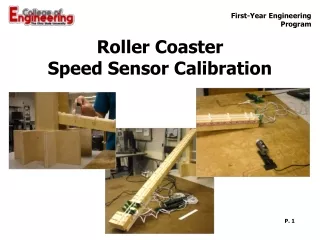
Roller Coaster Speed Sensor Calibration P. 1
Lab Safety • Do not stand on chairs, or sit or stand on the tables • Know the location of the first-aid kit • Report all injuries occurring in the lab to the instructional staff
Agenda • Background on Calibration • Overview of Lab • Physics Calculation Calibration Technique • Laser Calibration Technique • Camera Calibration Technique
Sensors • Many products use sensors • Some products use sensors to detect the presence of some condition, such as: • to automatically open doors when someone approaches • to change traffic signals when cars are waiting • These types of sensors typically have two states, “on” and “off”. P. 5
Sensors • Some products use sensors to measure and display physical characteristics such as temperature, weight, light intensity, etc. • This type of sensor must: • reliably and repeatably create a signal directly related to the characteristic being measured • be calibrated against a known standard so that the readout is accurate P. 6
Roller Coaster Sensor • The roller coaster project will use sensors to measure the speed of the ball at eight locations on the track. • This lab will illustrate three different techniques for calibrating these speed sensors. P. 7
Coaster Application Software • On the lab computers is a software application called “Coaster.” It measures up to eight sensors’ outputs and records the pulse duration for each. • The speed is found by dividing the diameter of the ball by the pulse duration. P. 8
Coaster Application Software • This software is designed to accept a correction factor for determining the accurate speed of the ball passing through the sensors. • This lab uses three different techniques for determining this correction factor. P. 9
Calculating Speeds The clear plastic around the LED is a lens that focuses the light into a beam. The beam has a spread of about 6 degrees. Because of this and because the edges of the ball are not flat, the measured time is shorterthan the actual time.
Diameter of Ball (D) Trailing Edge Leading Edge Measure (t2-t1) Time axis SPEED CALCULATIONS The correction factor for the LED/Phototransistor pair and the 1” Dia. coaster ball was measured to be 8.3%. So the speed can be calculated using: s=D/[1.083*(t2-t1)]
Technique 1 – Physics Calculations • You will calculate values of speed based on physics principles compared to the speed measured by the software. • You will analyze the results and determine a correction factor to calibrate the speed sensor. P. 12
Physics CalculationsBall rolling down a ramp Total energy at top of ramp = Potential Total energy at bottom of ramp = Translational Kinetic plus rotational kinetic Conservation of Energy (including rolling friction losses and assuming there is no sliding) Solving for ball velocity at the bottom of ramp P. 13
Physics Calculation Technique Lowest rung Highest rung P. 14 Middle rung
Technique 2 – Laser Calibration • Use two, small-beam lasers equally-spaced on either side of the speed sensor to measure the average speed between the sensors. • Use the average speed as a good estimate of the true speed at the speed sensor. • Create a correction factor based on the data from the lasers and their software. P. 15
MATLAB Calibration Displayof Laser Output Leading edge of laser pulse 1 Trailing edge of laser pulse 1 Laser Leading edge for LED Sensor LED Speed Sensor Trailing edge for LED Sensor P. 18
Technique 3 – Video capture • Use a camera and computer to capture video images at a known rate of frames per second. • Measure how far the ball travels between frames near the speed sensor to determine its accurate speed. • Determine a correction factor based on this technique. P. 20
Camera Calibration Technique Needed Adjustment Camera Setup P. 21
Measurement of ball position Click here to move the menu. 144 mm. Align the left edge of the “Play Speed Settings” Menu with the leading of the ball to obtain an accurate position of the ball. P. 22
Analysis of Camera Data • Finding the position of the ball for all frames with the ball in view allows you to generate a graph of speed vs. position. • The linear trend from this data can be extrapolated to find the speed of the ball at the LED Speed Sensor. P. 23
Lab logistics • Each group will record their data on the spreadsheet at each piece of equipment in their supergroup. • The instructor will provide the spreadsheets at each table and collect and send the composite results to all students. P. 24
Bring It All Together • The correction factor for each method is determined by calculating the ratio of the measured speed for each calibration technique to the measured speed of the LED speed sensor. P. 25
Assignment Due Today: • Initial Paper Design • Place Project Notebook on the table for check-up
Assigned Work: • Lab Memo • At the end of your lab procedure, review the requirements for the lab memo • Also review the grading guideline for point allocation. Next week due: Circuit Prototyping Lab Memo & Sensor Calibration Lab Memo