Download
1 / 53
530 likes | 562 Views
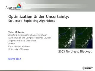
Large Transmission Pipeline Operations: Optimization under Future Uncertainty. Richard G. Carter and Henry H. Rachford, Advantica Todd Dupont, U. Chicago. Oil and Gas Pipelines. Liquid Pipelines Natural Gas Pipelines. Gathering systems Cross-country Transmission systems

E N D
Large Transmission Pipeline Operations: Optimization under Future Uncertainty Richard G. Carter and Henry H. Rachford, Advantica Todd Dupont, U. Chicago
Liquid Pipelines Natural Gas Pipelines Gathering systems Cross-country Transmission systems Distribution systems Taxonomies
General Themes for this Talk • Gas Transmission Pipeline • Transient vs steady state analysis • Optimal planning for operation under stressful conditions • Optimal Preparation under Uncertainty
Overview • Today’s Goal: Describe a class of problems that occur in our industry and some of the results that can be obtained. • We first present a Sample Pipeline, some of the physical aspects of the problem, and show optimal operation given 2 different scenarios • Robust solution that allows for either scenario. • What does uncertainty mean to us? Recourse? • Observations and Conclusions
What is a pipeline? Pipes Compressors Sources and deliveries
Frictional Pressure Losses Compressor Station Pipe Pipe Frictional Pressure Drop – Function of Flow rate, diameter, coating, etc Frictional Pressure Drop Pressure Added –Costs Energy and $
Many Physical Constraints Compressor Station Pipe Pipe Installed Power, Shaft Torque, Case Pressures, etc MAOP, MINP, ETC MAOP, MINP, ETC
Operational Implications Compressor Station Pipe Pipe Constraints MAOP, MINP, ETC MAOP, MINP, ETC
Operational Implications Some days it’s easy to satisfy constraints Some days it’s hard or impossible
New loads always draw on line pack Gas does not instantaneously transport itself 600 miles when the side load comes online!
Sample problem attributes We have 1000 Miles of pipe initially operating at about 95% of maximum attainable steady state flow. 25 Compressor stations of 25,000 HP each operating in a time dependent manner to overcome frictional pressure losses while avoiding maximum and minimum pressure limits. To put this into perspective, note that this sample transmission pipeline has installed compressor power roughly equivalent to the power plants of 200 locomotives, or of 2 Nimitz class nuclear aircraft carriers. The work that can be performed over a one day period is also comparable to that expended in 2 space shuttle launches. Construction costs for such a pipeline are on the order of 2 billion dollars. For further perspective, note that this example is small compared to major North American lines, which may have an order of magnitude more capacity.
Sample problem attributes We consider a transient side load that temporarily puts the pipeline at over 115% of it’s steady capacity. This “insanely difficult” challenge is actually becoming common due to the increased usage of natural gas fired “peaking electric power plants.” This is possible because of “line-pack” manipulation – mass and energy stored in the pipeline itself.
Today’s example: 25 Station Pipeline TWO POTENTIAL SIDE DELIVERIES
Technical Assumptions • As always, we use full nonlinear partial differential equation model for pipeline hydraulics. • Realistic equipment models are used including realistic system limitations.
First: Scheduled Side Loads • Assume an upcoming plant load is completely predictable. • For success, the load must be delivered fully and smoothly using only available compression, without violating any pressure limitations anywhere in the system, and the desired final state must be achieved by the end of the day.
Optimal Pack Redistribution • We know with certainty that the power plant at Station 17 is coming online at 2PM. • Where should we place line pack to get ready? • How do we get it there using only available compression and without violating limits? • How do we use it after the load comes on?
Initially 95% loaded, Jumps to over 115% during side delivery LOAD COMING AT 2PM AT STATION 17 Always remember gas does not instantaneously transport itself 600 miles when the side load comes online!
General problem form • minimize f(S) s/t • S = s(x;L) where • S is the system state (pressures in space and time) • s is the simulation (coupled system of PDEs) • x is the control vector (compressor settings in space and time) • L is the set of boundary conditions (upcoming load patterns in space and time) • Equipment Constraints • Min and Max Pressure Constraints, etc.
Initially 95% loaded, Jumps to over 115% during side delivery LOAD COMING AT 2PM AT STATION 17
Why does pack redistribution help? • Puts the mass at the right place at the right time. • Energy stored as compression can have the effect of (temporarily) geographically redistributing the power available to move gas.
How do we achieve this pack? • The software provides operators with a schedule of set points. • Discharge pressure is used in our example but other controls are trivially available. • The set points are our controlplan and the evolving line pack is the hydraulic consequence of following this plan.
Another possible side load SIDE LOAD, 20% TOTAL SYSTEM CAPACITY, 384 miles from previous example
Power Plant at Station 7 • Example 2 • Suppose the upcoming load is at station 7 rather than station 17. • This is 384 miles (640 KM) from the load in our previous example. • How would our optimal line pack preparation differ?
Peaking Gas-Fired Power Plant Loads TWO POTENTIAL SIDE DELIVERIES Which actually occurs will depend on weather, electric spot market prices, stock market, etc
Uncertainty • Assume we only know what loads are possible later today rather than having absolute certainty. • Preparing for one particular eventuality, even if it is most likely, may be exactly the wrong thing to do to prepare effectively for other possibilities. • Transient optimization with hedging can be used to optimally position line pack to prepare for such loads.
General problem form • minimize f(S,T) s/t • S = s(x;L) for control x and boundary conditions L • T = s(y;M) for control y and boundary conditions M • x and y are forced to be identical before the load onset but recourse is allowed afterwards • Plus other normal constraints on S, T, equipment, etc.
Uncertainty • “Uncertainty” in today’s talk doesn’t mean we don’t know what range of events is likely to happen. • It just means we don’t really know whether any particular event will unfold at a precisely predictable time and place. • Terminology: Epistemic or Aleatory?
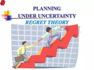
Discussion Comparison with other engineering approaches to dealing with uncertainty An Analogy
HEDGING TO PLAN FOR UNCERTAIN FUTURE EVENTS Mt Fuji WEST TOKYO AN ANALOGY EAST TOKYO
ARMY Mt Fuji PLAN A MAKE BEST GUESS AND COMMIT YOUR FORCES WEST TOKYO EAST TOKYO
ARMY ARMY Mt Fuji PREPARATION USING 50-50 SPLIT MAY FARE NO BETTER WEST TOKYO EAST TOKYO
ARMY ARMY Mt Fuji INCREASING SIZE OF ARMY DOES NOT NECESSARILY TRANSLATE INTO MORE SAFETY. WEST TOKYO EAST TOKYO
Observations • Planning for only one eventuality can lead to poor performance or even failure should another one occur. • Naïve planning for several eventualities can also lead to poor performance. • Increasing operational safety margins increases cost, but may or may not help with dependability.
ARMY ARMY ARMY Mt Fuji WEST TOKYO EAST TOKYO HEDGED SOLUTION AFTER DEFENSIVE PLAN EXECUTED
Other examples of optimal preparation • First two examples showed optimal preparation for two different, challenging scenarios where possible loads were separated in space. • Third example showed a hedged solution that effectively prepared for either example. • What else might we profitably hedge against? How about uncertainty in both space and time?
Paying the Piper • In hedging, you traditionally have to give up something to get your benefits. • This is expected in hedged transient pipeline optimization as well. • In our enclosed examples, the extra energy cost for a hedged solution versus a known-future solution was tiny. • We don’t expect that to always be true.
Conclusions • Transient optimization allows some rather remarkable things to be done with pack management. • For the applications of most interest to us, “optimization under uncertainty” is about defensive preparation for large discrete events that we know may happen, rather than optimization over a distribution of possibilities. • Hedging is a promising tool for managing this type of uncertainty.