Download
1 / 49
500 likes | 567 Views
Anti-parallel versus Component Reconnection at the Magnetopause. K.J. Trattner Lockheed Martin Advanced Technology Center Palo Alto, CA, USA and the Polar/TIMAS, Cluster/CIS, Image/FUV teams. Outline. Reconnection: When, Where and Why Where: The Cusp for Northward IMF

E N D
Anti-parallel versus Component Reconnectionat the Magnetopause K.J. Trattner Lockheed Martin Advanced Technology Center Palo Alto, CA, USA and the Polar/TIMAS, Cluster/CIS, Image/FUV teams
Outline • Reconnection: When, Where and Why • Where: The Cusp for Northward IMF - Anti-parallel Reconnection - Component Reconnection • Where: The Cusp for Southward IMF - Component Reconnection - Anti-parallel Reconnection • Summary
Magnetic Reconnection • When does reconnection occur – “all the time” (i.e., it is a “quasi-steady” process) • We have poor knowledge of the changes in the reconnection rate • Where does reconnection occur – recent observations appear to favor anti-parallel reconnection but some previous observations suggest component reconnection • Work in progress……. Stay tuned! • Why does reconnection occur – DON’T KNOW! • The answer appears to be in the electron diffusion region • Future mission (e.g., MMS) will have the time resolution and instrumentation to fully investigate this region
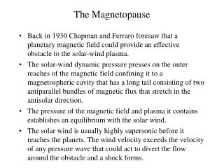
Magnetic Reconnection Near the Earth: Field Line Topologies (for Southward IMF) Magnetopause Current Sheet Blue - Solar Wind Field Lines Green - Closed Field Lines Red - Open Field Lines Focus on “dayside” reconnection
Observe Reconnection In Two Locations • Cusp: “foot” of the reconnected field lines • Does reconnection stop? • Where does reconnection occur? Each location has its advantages and disadvantages • Magnetopause: “up close and personal” • What is the reconnection rate? • Where does reconnection occur?
WHEN:Low- and High Altitude Cusp Observations MLT = 3h UT = 5h Trattner et al. [2002]
Direct Confirmation of Images of the Foot of a Reconnecting Field Line • Images of the footpoint from • the IMAGE spacecraft • Simultaneous observations • at the reconnection site from • the Cluster spacecraft • (bi-directional ion flows) • Magnetic field mapping • confirms the location of the • ionospheric “spot” Observations Mapping
IMF Rotation from North to South: Observations and Predictions Although there is a delay, in general, there is a simple change in the location of the reconnection site
IMF Rotation from South to North: Observations and Predictions Similar for south to north transition – a delay but reconnection does not stop, even when conditions change
“WHERE is reconnection occurring?” boils down to two models….
Remote Sensing the High Latitude Reconnection Site Magnetopause IMAGE spacecraft Sunward Convection Produces Two Effects: Auroral “Spot” in the Ionosphere Velocity Dispersion in the Cusp
Proton aurora images from IMAGE/FUV taken just before and after the arrival of an interplanetary disturbance in the ionosphere. Fuselier et al. [2002]
Mapping cusp foot points along geomagnetic field lines into the magnetosphere (Fuselier et al. [1994]).
Comparison of the location of field lines mapped from the cusp foot points with the location of anti-parallel reconnection sites.
The Location of the Reconnection Line for Northward IMFPolar/TIMAS Cusp Crossings • 240 Cusp Events for Northward IMF. • 81 events analyzed. • Calculate the Distance to the X-Line. • Mapping the Distance along the Geomagnetic Field.
Ion Dispersion in the Cusp: Distance to the Reconnection Site Assumes: “Instantaneous” Acceleration Simple Field Line Structure
Xr/Xm = 2Ve/(Vm-Ve) Onsager et al. [1990] Fuselier et al. [2000]
The Location of the Reconnection Line for Northward IMF Event 1: Sept. 22, 1997
Time (UT) Convection time to the MP: 22min
Tsyganenko [1996] together with Cooling [2001] IMF draping model
The Location of the Reconnection Line for Northward IMF Event 2: Oct. 30, 1997
81 events analysed 67 events with useable 3D cutoffs 29 antiparallel, 23 component, 15 >>Bx
Southward IMF: Anti-Parallel and Component Reconnection View from the Sun Can we determine the distance THAT accurately?
Precipitation is Different for the Two Types of Reconnection Anti-Parallel Tilted Line The Key Difference is The Flux Near Noon
Example: “Double Cusp” Interval – Component or Anti-Parallel? Trattner et al. (2003) showed these are spatial features (energy-time(latitude) dispersion indicative of reconnection) Compute the distance to the reconnection site for the two dispersions and see if they are different First dispersion Second dispersion
Two Different Distances for the Two Dispersions First Dispersion Second Dispersion (One distance for each measured distribution function) The second dispersion occurred closer to the spacecraft than the first dispersion Compare these distances to predictions from anti- Parallel reconnection Cluster View from the Sun
How Do the Distances Compare with Anti-Parallel Reconnection? “Red” = Anti-Parallel Reconnection Doesn’t compare Exactly with Anti- Parallel Reconnection Second Dispersion First Dispersion Get Some Help With the Interpretation….
The Cusp Images Tell the Difference Anti-Parallel Tilted Neutral Line Observations Looks more like anti- parallel reconnection but with a shift relative to local noon
Conclusion: Anti-Parallel Reconnection (with a Local Noon Shift) The pure T96 model does not show how the northern hemisphere reconnection line is shifted ~1/2 hour pre-noon However, the cusp images do! Second Dispersion First Dispersion
Summary • NORTHWARD IMF: Image/FUV and Polar/TIMAS observations reveal that both reconnection scenarios occur simultaneously. • SOUTHWARD IMF: Both reconnection scenarios observed. Unclear what triggers one or the other.
Anti-Parallel Reconnection for Northward IMF Northward IMF Magnetopause antiparallel Solar Wind Z reconnection Magnetic sites Field Solar Wind Earth's Magnetic Y cusps Field in the Magnetosphere magnetosheath field View of the Dayside magnetopause from the Sun
Northward IMF Poleward Reconnection Site Equatorward Reconnection Site Observations in the cusp have indicated the possibility of component reconnection for northward IMF (e.g., Onsager and Fuselier, 1994; Chandler et al., 1999; Fuselier et al., 2000)