Download
1 / 32
340 likes | 615 Views
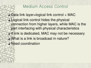
Medium Access Schemes. Media Access: Motivation. The problem: multiple users compete for a common, shared resource (medium) Can we apply media access methods from fixed networks? Example: CSMA/CD C arrier S ense M ultiple A ccess with C ollision D etection (IEEE 802.3)

E N D
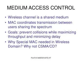
Media Access: Motivation The problem: multiple users compete for a common, shared resource (medium) Can we apply media access methods from fixed networks? Example: CSMA/CD • Carrier Sense Multiple Access with Collision Detection(IEEE 802.3) • send as soon as the medium is free (carrier sensing – CS) • listen to the medium, if a collision occurs stop transmission and jam (collision detection – CD) Problems in wireless networks • signal strength decreases (at least) proportional to the square of the distance • the sender would apply CS and CD, but the collisions happen at the receiver • it might be the case that a sender cannot “hear” the collision, i.e., CD does not work • furthermore, CS might not work if, e.g., a terminal is “hidden” Advanced Mobile Communication Networks, Master Program
Motivation - hidden and exposed terminals Hidden terminals • A sends to B, C cannot receive A • C wants to send to B, C senses a “free” medium -> CS fails • collision at B, A cannot receive C -> CD fails • A is “hidden” for C Exposed terminals • B sends to A, C wants to send to another terminal (not A or B) • C has to wait, CS signals a medium in use • but A is outside the radio range of C, therefore waiting is not necessary • C is “exposed” to B A B C A B C Advanced Mobile Communication Networks, Master Program
Motivation - near and far terminals Terminals A and B send, C receives • signal strength decreases proportional to the square of the distance • the signal of terminal B therefore drowns out A’s signal • C cannot receive A If C for example was an arbiter for sending rights, terminal B would drown out terminal A already on the physical layer Also severe problem for CDMA-networks – precise power control needed! A B C Advanced Mobile Communication Networks, Master Program
Access methods SDMA/FDMA/TDMA SDMA (Space Division Multiple Access) • segment space into sectors, use directed antennas • cell structure FDMA (Frequency Division Multiple Access) • assign a certain frequency to a transmission channel between a sender and a receiver • permanent (e.g., radio broadcast), slow hopping (e.g. GSM), fast hopping (FHSS, Frequency Hopping Spread Spectrum) TDMA (Time Division Multiple Access) • assign the fixed sending frequency to a transmission channel between a sender and a receiver for a certain amount of time The multiplexing schemes presented previously are now used to control medium access! Advanced Mobile Communication Networks, Master Program
Communication link types Each terminal needs an uplink and a downlink channel Types of communication links: • Simplex • unidirectional link transmission • Half Duplex • Bi-directional (but not simultaneous) • Duplex • simultaneous bi-directional link transmission, two types: • Frequency division duplexing (FDD) • Time division duplexing (TDD) downlink uplink Advanced Mobile Communication Networks, Master Program
Td Tu Td Fd Tu Fu Duplex modes • Frequency Division Duplex (FDD) • Separate frequency bands for up- and downlink • + separation of uplink and downlink • interference • no support for asymmetric traffic • Examples: LTE, UMTS, GSM, IS-95,AMPS • Time Division Duplex (TDD) • Separation of up- and downlink traffic on time axis • + support for asymmetric traffic • mix of uplink and downlink interference on single band • Examples: DECT, WLAN, UMTS (TDD), TD-LTE Advanced Mobile Communication Networks, Master Program
FDD/FDMA - general scheme, example GSM f 960 MHz 124 downlink 200 kHz 935.2 MHz 1 20 MHz 915 MHz 124 uplink 890.2 MHz 1 t Advanced Mobile Communication Networks, Master Program
TDD/TDMA - general scheme, example DECT 417 µs 1 2 3 11 12 1 2 3 11 12 t downlink uplink Advanced Mobile Communication Networks, Master Program
TDMA: Aloha/slotted aloha Mechanism • random, distributed (no central arbiter), time-multiplex • Slotted Aloha additionally uses time-slots, sending must always start at slot boundaries Aloha Slotted Aloha collision sender A sender B sender C t collision sender A sender B sender C t Advanced Mobile Communication Networks, Master Program
TDMA: Demand Assigned Multiple Access (DAMA) Channel efficiency only 18% for Aloha, 36% for Slotted Aloha (assuming Poisson distribution of packet arrivals and packet lengths) Reservation can increase efficiency to 80% • a sender reserves a future time-slot • sending within this reserved time-slot is possible without collision • reservation also causes higher delays • typical scheme for satellite links (long round-trip-times) • application to packet data, e.g. in GPRS and UMTS Examples for reservation algorithms: • Explicit Reservation (Reservation-ALOHA) • Implicit Reservation (PRMA) • Reservation-TDMA Advanced Mobile Communication Networks, Master Program
TDMA: DAMA – Explicit Reservation based on Aloha Explicit Reservation (Reservation Aloha): Two modes: • ALOHA mode for reservation:competition for small reservation slots, collisions possible • reserved mode for data transmission within successful reserved slots (no collisions possible) synchronisation: it is important for all stations to keep the reservation list consistent at any point in time and, therefore, all stations have to synchronize from time to time collision t Aloha reserved Aloha reserved Aloha reserved Aloha Advanced Mobile Communication Networks, Master Program
frame2 A C A B A frame3 A B A F frame4 A B A F D frame5 A C E E B A F D TDMA: DAMA – Implicit Reservation (PRMA) Implicit reservation (PRMA - Packet Reservation MA): • a certain number of slots form a frame, frames are repeated • stations compete for empty slots according to the slotted aloha principle • once a station reserves a slot successfully, this slot is automatically assigned to this station in all following frames as long as the station has data to send • competition for these slots starts again as soon as the slot was empty in the last frame implicit reservations 1 2 3 4 5 6 7 8 time-slot ACDABA-F frame1 A C D A B A F ACDABA-F collision at reservation attempts AC-ABA-- A---BAF- A---BAFD ACEEBAFD t New successful reservation attempts are in bold letters Advanced Mobile Communication Networks, Master Program
TDMA: DAMA – Reservation-TDMA Reservation Time Division Multiple Access • every frame consists of N mini-slots and x data-slots • every station has its own mini-slot and can reserve up to k data-slots using this mini-slot (i.e. x = N * k) • other stations can send data in unused data-slots according to a round-robin sending scheme (best-effort traffic) • Advantage: (small) guaranteed bandwidth with small latency for each station • Disadvantages:fixed number of stations (mini slots); global coordination e.g. N = 6 stations, k = 2 data slots per station N * k data-slots N mini-slots reservationsfor data slots other stations can use free data-slots based on a round-robin scheme Advanced Mobile Communication Networks, Master Program
TDMA: Multiple Access with Collision Avoidance (MACA) Motivation: deal with hidden terminals without a base station (central controller) MACA (Multiple Access with Collision Avoidance) uses short signaling packets for collision avoidance • RTS (request to send): a sender requests the right to send from a receiver with a short RTS packet before it sends a data packet • CTS (clear to send): the receiver grants the right to send as soon as it is ready to receive • all other stations listen to the signal Signaling packets contain • sender address • receiver address • packet size Collision may occur during transmission of RTS signal only but this is small compared to the data transmission Advanced Mobile Communication Networks, Master Program
A A C C TDMA: MACA examples MACA avoids the problem of hidden terminals • A and C want to send to B • A sends RTS first • C waits after receiving CTS from B MACA avoids the problem of exposed terminals • B wants to send to A, C to another terminal • B sends RTS, A replies with CTS • C does not receive CTS from A => C concludes that it is not within receiving range of A • C can start its transmission Disadvantage: • overhead where data packets are small RTS CTS CTS B RTS RTS CTS B Advanced Mobile Communication Networks, Master Program
TDMA: MACA variant: DFWMAC in IEEE 802.11 Simplified state machine receiver sender idle idle packet ready to send; RTS data; ACK RxBusy time-out; RTS wait for the right to send RTS; CTS time-out incorrect data; NAK ACK time-out NAK; RTS CTS; data wait for data wait for ACK RTS; RxBusy ACK: positive acknowledgement NAK: negative acknowledgement RxBusy: receiver busy Advanced Mobile Communication Networks, Master Program
TDMA: Polling mechanisms If one terminal can be heard by all others, this “central” terminal (e.g. a base station) can poll all other terminals according to a certain scheme • now all schemes known from fixed networks can be used (typical mainframe - terminal scenario, round-robin, random, reservation-based) Example: Randomly Addressed Polling • base station signals readiness to all mobile terminals • terminals ready to send can now transmit a random number without collision with the help of CDMA or FDMA (the random number can be seen as dynamic address) • the base station now chooses one address for polling from the list of all received random numbers (collision if two terminals choose the same address) • the base station acknowledges correct packets and continues polling the next terminal • this cycle starts again after polling all terminals of the list Application to Bluetooth and 802.11 (possible access function) Advanced Mobile Communication Networks, Master Program
TDMA: ISMA (Inhibit Sense Multiple Access) Current state of the medium is signaled via a “busy tone” • the base station signals on the downlink (base station to terminals) if the medium is free or not • terminals must not send if the medium is busy • terminals can access the medium as soon as the busy tone stops • the base station signals collisions and successful transmissions via the busy tone and acknowledgements, respectively (media access is not coordinated within this approach) • mechanism used, e.g. for CDPD (AMPS) Advanced Mobile Communication Networks, Master Program
CDMA access method CDMA (Code Division Multiple Access) • all terminals send on the same frequency probably at the same time and can use the whole bandwidth of the transmission channel • each sender has a unique random number, the sender XORs the signal with this random number • the receiver can “tune” into this signal if it knows the pseudo random number, tuning is done via a correlation function Advantages: • all terminals can use the same frequency, less planning needed • huge code space (e.g. 232) compared to frequency space • interference (e.g. white noise) is not coded • forward error correction and encryption can be easily integrated Disadvantages: • higher complexity of a receiver (receiver cannot just listen into the medium and start receiving if there is a signal) • all signals should have the same strength at a receiver (power control) Advanced Mobile Communication Networks, Master Program
CDMA principle sender (base station) receiver (terminal) Code 0 Code 0 data 0 data 0 Code 1 Code 1 Transmission via air interface S data 1 data 1 Code 2 Code 2 data 2 data 2 Advanced Mobile Communication Networks, Master Program
spreading spreaded signal CDMA by example data stream A & B Advanced Mobile Communication Networks, Master Program
decoding and despreading + transmission and distortion (noise and interference) overlay of signals CDMA by example Advanced Mobile Communication Networks, Master Program
CDMA in theory Sender A • sends Ad = 1, key Ak = 010011 (i.e. -1 1 -1 -1 1 1) • sending signal As = Ad * Ak = (-1, +1, -1, -1, +1, +1) Sender B • sends Bd = 0, key Bk = 110101 (i.e. 1 1 -1 1 -1 1) • sending signal Bs = Bd * Bk = (-1, -1, +1, -1, +1, -1) Both signals superimpose in space • interference neglected (noise etc.) • As + Bs = (-2, 0, 0, -2, +2, 0) Receiver wants to receive signal from sender A • apply key Ak bitwise (inner product) • Ae = (-2, 0, 0, -2, +2, 0) Ak = 2 + 0 + 0 + 2 + 2 + 0 = 6 • result greater than 0, therefore, original bit was „1“ • receiving B • Be = (-2, 0, 0, -2, +2, 0) Bk = -2 + 0 + 0 - 2 - 2 + 0 = -6, i.e. „0“ Advanced Mobile Communication Networks, Master Program
CDMA on signal level I data A Ad 1 0 1 Code A code sequence A Ak 0 1 0 1 0 0 1 0 0 0 1 0 1 1 0 0 1 1 1 0 1 0 1 1 1 0 0 0 1 0 0 0 1 1 0 0 data code As signal A Real systems use much longer keys resulting in a larger distance between single code words in code space Advanced Mobile Communication Networks, Master Program
CDMA on signal level II As signal A Bd 1 0 0 data B key B 0 0 0 1 1 0 1 0 1 0 0 0 0 1 0 1 1 1 Bk key sequence B 1 1 1 0 0 1 1 0 1 0 0 0 0 1 0 1 1 1 data key Bs signal B 1 0 -1 As + Bs Advanced Mobile Communication Networks, Master Program
CDMA on signal level III Ad data A 1 0 1 1 0 -1 As + Bs 1 -1 Ak 1 0 -1 (As + Bs) * Ak integrator output 0 1 1 comparator output Advanced Mobile Communication Networks, Master Program
CDMA on signal level IV data B Bd 1 0 0 1 0 -1 As + Bs 1 -1 Bk 1 0 -1 (As + Bs) * Bk integrator output 0 0 1 comparator output Advanced Mobile Communication Networks, Master Program
CDMA on signal level V 1 0 -1 As + Bs Assumptions • orthogonality of keys • neglectance of noise • no differences in signal level => precise power control 1 -1 wrong key K 1 0 -1 (As + Bs) * K integrator output comparator output (0) (0) ? Advanced Mobile Communication Networks, Master Program
Spread Aloha Multiple Access (SAMA) Motivation • Aloha has a very low efficiency • CDMA needs complex receivers to be able to receive different senders with individual codes at the same time Idea: use spread spectrum with only one single code (chipping sequence) for spreading for all senders accessing according to aloha collision sender A 1 0 1 narrowband sender B 0 1 1 send for a shorter period with higher power spread the signal e.g. using the chipping sequence 110101 („CDMA without CD“) t • Problem: find a chipping sequence with good characteristics • good autocorrelation for =0 • low autocorrelation for cases where phase differs from 0 Advanced Mobile Communication Networks, Master Program
Comparison SDMA/TDMA/FDMA/CDMA Advanced Mobile Communication Networks, Master Program
References Jochen Schiller: Mobile Communications (German and English), Addison-Wesley, 2000 (most of the material covered in this chapter is based on the book) Ramjee Prasad, Marina Ruggieri: Technology Trends in Wireless Communications, Artech House, 2003 Advanced Mobile Communication Networks, Master Program