Download
1 / 37
370 likes | 545 Views
i - Intelligent V - Valve P - Pack. iVP Function. The iVP is an integrated family of components offering: Operation at depths up to 3000 metres. Remote control of hydraulic and electrical equipment.

E N D
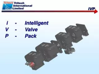
i - Intelligent V - Valve P - Pack
iVP Function • The iVP is an integrated family of components offering: • Operation at depths up to 3000 metres. • Remote control of hydraulic and electrical equipment. • Collection and transmission of instrumentation datafrom the remote location, including video. • Function control, data display and storage at a controlconsole. • Available from stock parts – fast deliveries.
iVP Applications • Remotely operatedvehicle (ROV) equipment. • Intervention tooling equipment. • Remotely operated tools (ROTs). • Manifold, pipeline & other underwater structures. • ROVs requiring additional or upgraded capability (e.g. 5-function manipulator enhancement). • Tether Management Systems (TMS).
Major component options • Valve Pack hydraulic modules for flow & pressurecontrol. • Valve Pack electronics module. • Simple Power Pod for valvepackpowersupplies. • Intelligent Power Pod for enhancedpower & control.
System Block Diagram Showing All Major Options.
Valve Pack physical • Lightweight aluminium construction, fully optimised to reduce size & weight • Modular design – configured for only the required number of functions. • Oil-filled pressure compensated internals (including electronics) – with depth rating of 3000 metres. • Hydraulic connections to suit host system requirements. • Hard anodised and CP bonded for corrosion protection. • Module lids removable quickly & separately for fast service. • Orientation insensitive.
Hydraulic Features • Modular design - 2, 4, 6, 8, 10 or 12 valves per valve pack. • Proportional directional valves give flow control from surface duringoperations withoutthe need for fixed flow throttles. • Flexible hydraulic specification offering: • Proportional or fixed flow directional valves in 2 flow sizes. • 1 or 2 separate pressure inputs, up to 315 bar. • Pressure control stages. • Service line relief valves for actuator / equipment protection. • Optional pilot operated check valves. • Optional hydraulic pressure transducers.
Electronics features • Embedded processors for instant boot-up and reliability. • Integrated communications link over 5.5km of twisted pair. • Software configurable mapping of console inputs to remoteunderwateroutputs (valve pack or power pod). • External sensors on both valve pack and power pod are supported(e.g. analogue, digital, CP, tacho, Torque Transducer). • Integrated embedded PC in console for display and user interface. • Video text overlay built into console. • System settings can be stored for configured operations. • Task specific settings can be saved and recalled. • Scaleable and upgradeable control system – from ‘dumb’ valve pack tocomplete control system. • Fully self contained system that does not rely upon the use of external computers.
Available iVP Modules • Electronics Module. • NG3 Directional Module. • Pressure Reducing Module. • NG6 Directional Module. • Torque Control Module. • Relief Valve Modules. • Mid Section Blanking Plate. • End Blanking plate.
Electronics Module • Proportional control of up to 12 directional valves & 1 pressure reducing valve. • +24V DC power input (700mA per valve). • External sensor interfaces as standard (analogue 12 & 16 bit, digital, water ingress) • 2 x Torque Tool sensor interfaces (turns, RPM & torque – software calibrated). • Optional depth transducer. • Fully protected circuits & status display LEDs • Embedded processor & integrated telemetry with Console and iPP. Full diagnostics.
Electronics Module Electronics Module circuit board stack
NG3 Directional Module • 3-position or 2-position directional valves • Proportional control (up to 8lpm). • ‘bang/bang’ control (up to 15lpm). • P.O. Check Valves – sandwich mounted (optional if required). • Service Line Relief Valves – externally mounted (optional if required). • Pressure Transducer Option. • Status LEDs & valve identification. • 2 x Water Ingress sensors
NG3 Directional Module Modules with interface PCBs and Lids removed
NG3 Directional Module NG3 Module Interface PCBs
Pressure Reducing Module • Reduces pressure to all downstream modules • Proportional Pressure Control (7 to 207bars) • Maximum flow 57 lpm • Upstream Pressure Transducer. • Downstream Pressure Transducer. • Status LEDs for valve drive & sensor outputs.
NG6 Directional Module • Proportional control (up to 40 lpm) • ‘bang/bangcontrol (up to 80 lpm) • Service Line Relief Valves externally mounted (if required). • Pressure Transducer Option. • Status LEDs & valve identification. • Applications – High flow functions (e.g. rotary tools, thrusters, motors). • Valves can be paralleled for double flow output.
Torque Control Module • Proportional directional valvefor tool speed & direction control (up to 40lpm) • Proportional Pressure Control for precise closed or open loop pressure or torque control (0-207bar) • High flow service-linerelief valves (ifrequired) – for interface protection. • Upstream Pressure Transducer. • DownstreamPressure Transducer.
Pressure Relief Modules • Fit below alldirectional valveor torque control modules. • Adjustable pressure relief to tank. • High and Low Flow Options. • Used to protect actuators & equipment.
Mid-section Blanking Plate • Inserted between two directional modules in the iVP stack. • Allowsmultiple pressure inputs or separate oil supplies. • Two types available – common return gallery & isolated return gallery.
End Blanking Plate • Completes the iVP stack. • Hydraulic connections for split supplies.
iVP Control Console Features • 2U 19” rack mounted unit, only 135mm behind panel. • 2 x 3-axis analogue joystick controllers. • 6 x Pushbutton & potentiometer pairs. • Any console control can be assigned to any valve (via software). • Insertable printed legend for pushbuttons. • Embedded processor for reliability & speed. Instant start-up. • Embedded PC in console for graphics display of sensor & system status – running on robust OS. • PSX Pad hand-controller assignable to valve or power pod functions. • Integrated video overlay.
iVP Control Console Flexible controllers
iVP Control ConsoleSoftware Console Status – shows valve allocations& status
iVP Control ConsoleSoftware iVP Status – shows valve allocations& status
iVP Control ConsoleSoftware Torque Tool Control
iVP Control ConsoleTelemetry Options • iVP Control console is ‘topside master’ • one iVP or iPP is ‘subsea master’ • Additional iVPs can be ‘subsea slaves’ • Telemetry between console and ‘subsea master’ options: • U-Interface 5.5km full duplex over 1 twisted pair • RS232 (via host system comms multiplexer) • RS422 (via host system comms multiplexer) • Arcnet – compatible with Tritech Arcnet infrastructure • Fully isolated & protected telemetry. • Robust error-checking methods.
Intelligent Power Pod • Electrical Input 90-135v ac 50-60Hz @ 10A • 2 x Valve Pack outputs2 x 24Vdc @ 7A • Video Camera Supplies 2 x 24V, focus & zoom 2 x 24V with focus 2 x 24V fixed focus • Lighting 6 x dimmable switched250W, 110Vac • Video switching 6 x 6 cross-point matrix • Electrical Pan & Tilts2 @ 110V ac – with sensors 2 @ 24V dc • External Sensors (analogue, digital, CP etc.) • Embedded processor, integrated telemetry, vacuum valve & sensor, full diagnostics.
Simple Power Pod • Dual output: • Electrical Input 90-260v ac 50-60Hz @ 5A • 2 x Valve Pack outputs2 x 24Vdc @ 7A • Water ingress & vacuum sensors • Single output: • Electrical Input 90-260v ac 50-60Hz @ 2A • Valve Pack outputs1 x 24Vdc @ 6.5A • Water ingress & vacuum sensors
Intelligent Power PodConsole • 2U 19” rack mountable console. • Operates as ‘slave’ to iVP console. • Directly controls all iPP functions.
Contacts Tritech International Ltd., Peregrine Road, Westhill Business Park, Westhill, Aberdeen AB32 6JL. Tel. +44 (0)1224 744111 Fax +44 (0)1224 741771 E-mail: sales@tritech.co.uk www.tritech.co.uk