Download
1 / 35
360 likes | 394 Views
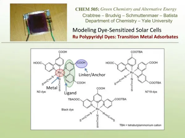
Growth and fabrication of dye sensitized solar cells on multilayer transparent conductive films. Dipti R. Sahu Department of Natural and Applied Sciences, Namibia University of Science and Technology, Windhoek, Namibia Email: dsahu@nust.na. Dye Sensitized Solar Cell (DSSC).

E N D
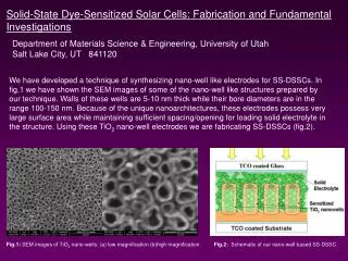
Growth and fabrication of dye sensitized solar cells on multilayer transparent conductive films Dipti R. Sahu Department of Natural and Applied Sciences, Namibia University of Science and Technology, Windhoek, Namibia Email: dsahu@nust.na
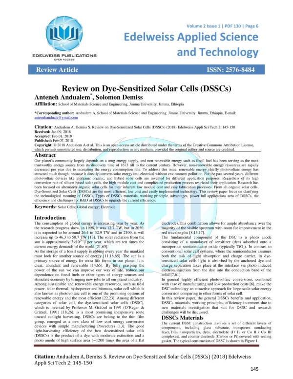
Dye Sensitized Solar Cell (DSSC) • Easy to be fabricated • Low cost • Friendly to the environment • Photo voltage is significantly less sensitive to light intensity variation than that of conventional solar cells
Low photocurrent could be the result of • Inefficient light harvesting by the dye • Inefficient charge injection into TiO2 • Inefficient collection of injection electron Principle of Dye-Sensitized Solarcells 1 1.Absorption 2. Electron injection 3. Regeneration 4. Cathode: Gratzel, Nature, 2001
Enhancement of injected electron collection • Multilayer nanocrystalline films with the structure of transparent conducting oxide/metal/transparent conducting oxide • ZnO/Ag/ZnO • Al-ZnO/Ag/Al-ZnO
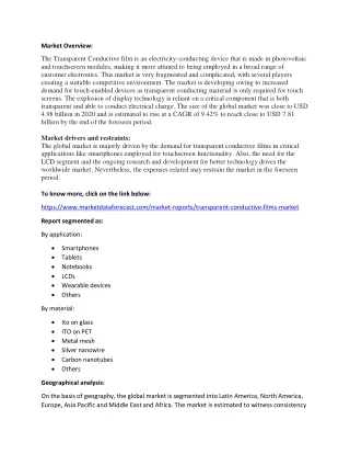
Transparent Conductor • A thin film is Transparent to visible light (220 -1100 nm) and conducting to electricity is called a Transparent Conductor • The basic Electromagnetic Theory does not permit a material to be both conducting and transparent simultaneously. • For example : Copper or Silver cannot be transparent • NaCl, CaF2, , In2O3, TiO2 cannot conduct !
The basic Physics of TCO Films: • Maxwells Equations demand that NO MATERIAL CAN BE BOTHTransparent (to visible light) and Conducting (to electricity) So How to get a Transparent Conductor ? • All Metal Oxides are Transparent • All Metals are conducting • Mix a Metal Oxide and a Metal !! Modify a transparent material for electrical conduction.
The TCO Thin films are • Wide band gap materials • Oxygen deficient • Just by varying oxygen content in the film (JUST ONE ELEMENT), the TCO can be made to exhibit: • Metallic • Semiconducting • Insulating Properties !!
Metal Oxides have a large Optical Band Gap Examples: Indium Oxide (In2O3) Zinc Oxide (ZnO) Tin doped Indium Oxide (ITO) and many more: all are metal oxides • Metal oxides are transparent to visible light (220 – 1100 nm). The optical band gap is 3.1 - 6.0 eV • They are all insulators • They are all stable inorganic materials
Why Multilayer with Metal interlayer • Very low sheet resistance • High optical transparency in the visible range • Relatively lower thickness than single layer • TCO films • 4. Better durability than single layer metal films.
Why ZnO/Ag/ZnO • ZnO is a transparent conductive oxide with a wide band gap (> 3.3ev) • Transparent in the wavelength region 350 to > 800nm and Wavelength cutoff depends on the charge carrier concentration. • Non toxicity, low cost, material abundance, high stability against hydrogen plasma and heat cycling. • Avoid series resistance effect. • Thin Ag film had good optical and electrical properties ,Ag has highest conductivity of all metals. To get improved cost effective transparent conductive material we chose ZnO based TCO with Ag as interlayer.
Transparent Conducting Oxide Thin Film • Al-doped ZnO (AZO) • ZnO/Ag/ZnO multilayer • AZO /Ag/AZO multilayer Preparation Conditions : • Target : ZnO (RF Sputtering), Ag (DC Sputtering) • AZO (sintered 2 wt % Al2O3 doped with ZnO: E-beam evaporation) • Pressure: 6×10⁻³ T, • Substrate Temp Variation : RT to 300C • Ar atmosphere: Variation from 20 to 50 sccm)
Transparent electrode for Dye Sensitized Solar Cells ZnO/Ag/ZnO ( ZnO =20nm and Ag =6nm) Transmittance = 90 % & Sheet resistance (Rs) = 3 /sq. = 1.4×10-5.cm
ZnO/Ag/ZnO multilayer Maximum transmittance 90% and Sheet resistance 3/sq. (Thickness of film : 46nm)
Thermal stability up to 4000C in all atmosphere ---- Suitable TCO for DSSC
Figure of Merit ( = T10/RSh) TC = 2.36×10⁻¹-1 higher than the maximum of existing conductive oxide films and multilayers. TC = 2 10-2 -1, Liu et al ,Thin Solid Films,441(2003)200
Al doped with ZnO (AZO) • 1000C (b) 1500C (c ) 2000C (d) 2500C • substrate temperature Resistivity: 2.5×10-4.cm and Transmittance > 80%
AZO / Ag / AZO multilayer AZO = 25 nm Importance of Ag layer thickness for maximum transmission Optimum thickness11 nm : T > 80 %
Al-doped (AZO) /Ag/AZO multilayer AZO = 25nm and Ag =11nm Transmittance = 90 % & Rs = 5.34 /sq. Thermal stability up to 5000C AZO/Ag/AZO shows better properties up to 5000C where as ZnO/Ag/ZnO multilayers shows up to 4000C.
ZAZ Multilayer with different thickness of ZnO surface Layer
AAA Multilayer with different thickness of AZO surface Layer
Light to energy conversion efficiencies of the DSSC with the thickness of the mesoporous TiO2 layer grown on ZAZ
Light to energy conversion efficiencies of the DSSC with the thickness of the mesoporous TiO2 layer grown on AAA
The current (I)- Voltage(V) graph of the DSSC fabricated with ZAZ,AAA, ITO and FTO glass
I-V Characteristics of DSSC fabricated using FTO, ITO, ZAZ, AAA and the mesoporous TiO2 electrodes. Measured under AM 1.5 (100 mW cm-2) Data are based on the averages of the dye sensitized cell samples; ranges of data are shown in parentheses
The I-V characteristics of DSSC with bare TiO2 and ZnO/TiO2 film electrodes on ZAZ and AAA. Max. Efficiency n(%) = 5.45 %
Conclusions • Suitable multilayer TCO electrode with sheet resistance of 7 /sq and transmittance of more than 85 % are synthesized for fabrication of DSSC. • The DSSC on AAO covered with ZnO/TiO2 film yielded an overall cell efficiency 5.45 %. • This developed multilayer TCO can be used as transparent electrode for making improved DSSC or plastic DSSC.