Download
1 / 35
550 likes | 1.52k Views
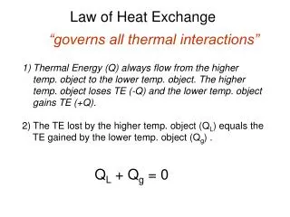
HEAT EXCHANGE EQUIPMENT. A 'heat exchanger' may be defined as an equipment which transfers the energy from a hot fluid to a cold fluid. Here, the process of heating or cooling occurs. In heat exchangers the temperature of each fluid changes as it passes through the exchangers. .

E N D
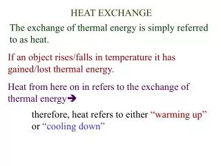
A 'heat exchanger' may be defined as an equipment which transfers the energy from a hot fluid to a cold fluid. Here, the process of heating or cooling occurs. In heat exchangers the temperature of each fluid changes as it passes through the exchangers.
General design of heat exchange equipment : • The design of heat exchange equipment is based on general principles. • From mass and energy balance HT area is calculated. • Quantities to be evaluated are U,LMTD. • In simple devices these quantities can be calculated accurately but in complex processing units the evaluation may be difficult and the final design is always a compromise based on engineering judgment to give best overall performance.
TYPES OF HEAT EXCHANGERS: 1.Doble pipe heat exchangers:
It consists of concentric pipes with standard return bends. • One fluid flows through inside metal pipe and the second fluid flows through the annulus between the outside pipe and inside pipe. • The flow directions may be either parallel or counter fashions. • These exchangers are used when heat transfer area required is not more than 150 sq.ft
Advantages; • 1. Simple in construction • 2. Cheap • 3. Very easy to clean • 4. Very attractive when required Heat transfer areas are small. Disadvantages: • 1. The simple double pipe heat exchanger is inadequate for large flow rates • 2. If several double pipes are used in parallel, the weight of metal required for the outer tubes becomes so large. • 3. Smaller heat transfer area in large floor space as compared to other types • 4. Leakage are more.
Shell and tube heat exchanger : • The simple double pipe heat exchanger is inadequate for large flow rates. If several double pipes are used in parallel, the weight of metal required for the outer tubes becomes so large. • When large areas are required we go for shell and tube heat exchangers. • It is the most common type of heat exchanger in oil refineries and other large chemical processes.
Shell and tube heat exchanger consists of a shell with a bundle of tubes inside it. • One fluid flows through the tubes (the tube side) and the other fluid flows outside the tubes but inside the shell (the shell side). • Heat is transferred from one fluid to the other through the tube walls, either from tube side to shell side or vice versa. • The fluids can be either liquids or gases on either the shell or the tube side.
Construction and parts: Shell: It is usually a cylindrical casing through which one of the fluid flows. Shell is commonly made of carbon steel. The minimum thickness of shell made of carbon steel varies from 5 mm to 11 mm depending upon the diameter.
Tubes: • Standard heat exchanger tubes which are used in many industrial processes may be of various sizes and lengths. • The wall thickness of tubes is usually expressed in terms of Birmingham Wire Gauge (BWG). • The thickness depends upon material of construction and diameter. • Standard lengths of tubes for heat exchanger construction are 8, 12, 16 and 20 ft.
Tube pitch: • The shortest centre-to-centre distance between the adjacent tubes is called as tube pitch. • Tubes arranged in a triangular or square layout, known as triangular or square pitch. • Square pitch gives lower shell side pressure drop than triangular pitch. • Square pitch is good for easy cleaning whereas triangular pitch gives more number tubes for same space available • Unless shell side fluid fouls badly, triangular pitch is used.
TEMA standards specify a minimum center to center distance 1.25 times outside diameter of the tubes for triangular pitch and a minimum cleaning lane of ¼ inch for square pitch.
Tube sheet: • It is essentially a flat circular plate. A large number of holes are drilled in the tube sheet according to the pitch requirements.
Baffles: The baffles are installed in the shell • To increase the rate of heat transfer by increasing the velocity and turbulence of the shell side fluid • It helps as structural supports for tubes and dampers against vibration. • The baffles cause the fluid to flow through shell at right angles to the axes of the tubes (Cross flow). OR They promote cross flow
To avoid the bypassing of the shell side fluid the clearance between the baffles and shell, and baffles and tubes must be minimum. • The centre-to-centre distance between adjacent baffles is known as baffle spacing or baffle pitch. • The baffle space should not be greater than the inside diameter of the shell and should not less than the one-fifth if the inside diameter of the shell. • The optimum baffle spacing is 0.3 to 0.50 times the shell diameter
Limitations: • It occupy more space • Cannot obtain high velocities hence low heat transfer coefficients. • No solution for expansion problems.
MULTI PASS HEAT EXCHANGERS: • Multi pass construction decreases the cross section of the fluid path and increases the fluid velocity and corresponding HT Coefficient Advantages: • High velocities • Short tubes • Solution to expansion problems
Disadvantages: • Exchanger is more complicated • Friction loss are increased because of high velocities, longer path ,multiplication of entrance and exit losses
2-4 Heat exchangers: • 1-2 heat exchanger has an important limitation. Because of parallel flow pass ,the exchanger is unable to bring one of the fluid very near to the entrance temperature of the fluid. OR The heat recovery is poor. So we go for 2-4 heat exchanger It gives high velocity and large HTC than 1-2 Exchanger with same flow rates.
Heat transfer coefficients in shell and tube heat exchangers: In a shell-and-tube exchanger, the shell-side and tube side heat transfer coefficients are of comparable importance and both must be large if a satisfactory overall coefficient is to be attained.
Gb Gc Gb
Exchanger Fouling Electron microscope image showing fibers, dust, and other deposited material on a residential air conditioner coil and a fouled water line in a water heater.