Download
1 / 270
2.72k likes | 2.83k Views
Secondary Storage Management. The Memory Hierarchy. The Memory Hierarchy. Computer systems have several different components in which data may be stored. Data capacities & access speeds range over at least seven orders of magnitude

E N D
Secondary Storage Management The Memory Hierarchy
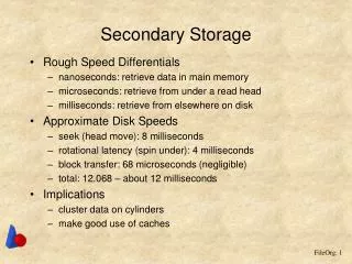
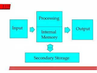
The Memory Hierarchy • Computer systems have several different components in which data may be stored. • Data capacities & access speeds range over at least seven orders of magnitude • Devices with smallest capacity also offer the fastest access speed • The term memory hierarchy is used in computer architecture when discussing performance issues in computer architectural design, algorithm predictions, • The lower level programming constructs such as involving locality of reference.
Description of Levels • Cache • Megabyte or more of Cache storage. • On-board cache : On same chip. • Level-2 cache : On another chip. • Cache data accessed in few nanoseconds. • Data moved from main memory to cache when needed by processor • Volatile
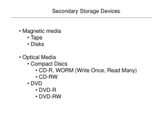
Description of Levels 2. Main Memory • 1 GB or more of main memory. • Instruction execution & Data Manipulation - involves information resident in main memory. • Time to move data from main memory to the processor or cache is in the 10-100 nanosecond range. • Volatile 3. Secondary Storage • Typically a magnetic disk. • Capacity upto 1 TB. • One machine can have several disk units. • Time to transfer a single byte between disk & main memory is around 10 milliseconds.
Description of Levels • Tertiary Storage • Holds data volumes measured in terabytes. • As capacious as a collection of disk units can be, there are databases much larger than what can be stored on the disk(s) of a single machine, or even several machines. • Significantly higher read/write times. • Tertiary storage is characterized by significantly higher read/write times than secondary storage • Smaller cost per bytes. • Retrieval takes seconds or minutes, but capacities in the petabyte range are possible.
Transfer of Data Between Levels • Data moves between adjacent levels of the hierarchy. • Each level is organized to transfer large amounts of data to or from the level below • Key technique for speeding up database operations is to arrange data so that when one piece of a disk block is needed • It is likely that other data on the same block will also be needed at about the same time.
Volatile & Non Volatile Storage • A volatile device “forgets” what is stored in it when the power goes off. • Example: Main Memory • A nonvolatile device, on the other hand, is expected to keep its contents intact even for long periods when the device is turned off or there is a power failure. • Example: Secondary & Tertiary Storage Note: No change to the database can be considered final until it has migrated to nonvolatile, secondary storage.
Virtual Memory • Managed by Operating System. • Typical software executes in virtual-memory, an address space that is typically 32 bits; • There are 232 bytes, or 4 gigabytes, in a virtual memory. • Some memory in main memory & rest on disk. • Transfer between the two is in units of disk blocks (pages). • Not a level of the memory hierarchy
Section 13.2 – Secondary storage management CS-257 Database System Principles Avinash Anantharamu (102) 008629907
Index • 13.2 Disks • 13.2.1 Mechanics of Disks • 13.2.2 The Disk Controller • 13.2.3 Disk Access Characteristics
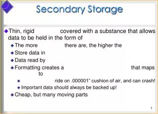
Mechanics of Disks • Two principal moving pieces of hard drive 1- Head Assembly 2- Disk Assembly • Disk Assembly has 1 or more circular platters that rotate around a central spindle. • Platters are covered with thin magnetic material • The upper and lower surfaces of the platters are covered with a thin layer of magnetic material,on which bits are stored. • 0’s and l ’s are represented by different patterns in the magnetic material. • A common diameter for disk platters is 3.5 inches, although disks with diameters from an inch to several feet have been built.
Mechanics of Disks • Tracks are concentric circles on a platter. • The two principal moving pieces of a disk drive - disk assembly and a head assembly. • The disk is organized into tracks, • Tracks are organized into sectors which are segments of circular platter. • In 2008, a typical disk has about 100,000 tracks per inch but stores about a million bits per inch along the tracks. • Sectors are indivisible as far as errors are concerned. • Blocks are logical data transfer units.
Disk Controller • Control the actuator to move head assembly • Selecting the surface from which to read or write • Transfer bits from desired sector to main memory • buffering an entire track or more in local memory of the disk controller • additional accesses to the disk can be avoided.
Disk Access characteristics • Seek time • Rotational latency • Transfer time • Latency of the disk.
13.3 Accelerating Access to Secondary Storage San Jose State University Spring 2012
13.3 Accelerating Access to Secondary StorageSection Overview • 13.3.1: The I/O Model of Computation • 13.3.2: Organizing Data by Cylinders • 13.3.3: Using Multiple Disks • 13.3.4: Mirroring Disks • 13.3.5: Disk Scheduling and the Elevator Algorithm • 13.3.6: Prefetching and Large-Scale Buffering
13.3 Introduction • Average block access is ~10ms. • Disks may be busy. • Requests may outpace access delays, leading to infinite scheduling latency. • There are various strategies to increase disk throughput. • The “I/O Model” is the correct model to determine speed of database operations • the scheduling latency becomes infinite.
13.3 Introduction (Contd.) • Actions that improve database access speed: • Place blocks closer, within the same cylinder • Increase the number of disks • Mirror disks • Use an improved disk-scheduling algorithm • Use prefetching • improve the throughput
13.3.1 The I/O Model of Computation • If we have a computer running a DBMS that: • Is trying to serve a number of users • Has 1 processor, 1 disk controller, and 1 disk • Each user is accessing different parts of the DB • It can be assumed that: • Time required for disk access is much larger than access to main memory; and as a result: • The number of block accesses is a good approximation of time required by a DB algorithm
13.3.2 Organizing Data by Cylinders • It is more efficient to store data that might be accessed together in the same or adjacent cylinder(s). • In a relational database, related data should be stored in the same cylinder. • we can approach the theoretical transfer rate for moving data on or off the disk.
13.3.3 Using Multiple Disks • If the disk controller supports the addition of multiple disks and has efficient scheduling, using multiple disks can improve performance significantly • By striping a relation across multiple disks, each chunk of data can be retrieved in a parallel fashion, improving performance by up to a factor of n, where n is the total number of disks the data is striped over • The disk controller, bus, and main memorycan handle n times the data-transfer rate, • n disks will have approximately the performance of one disk that operates n times as fast.
13.3.4 Mirroring Disks • A drawback of striping data across multiple disks is that you increase your chances of disk failure. • To mitigate this risk, some DBMS use a disk mirroring configuration • Disk mirroring makes each disk a copy of the other disks, so that if any disk fails, the data is not lost • Since all the data is in multiple places, access speedup can be increased by more than n since the disk with the head closest to the requested block can be chosen
13.3.5 Disk Scheduling • One way to improve disk throughput is to improve disk scheduling, prioritizing requests such that they are more efficient • The elevator algorithm is a simple yet effective disk scheduling algorithm • The algorithm makes the heads of a disk oscillate back and forth similar to how an elevator goes up and down • The access requests closest to the heads current position are processed first
13.3.5 Disk Scheduling • When sweeping outward, the direction of head movement changes only after the largest cylinder request has been processed • When sweeping inward, the direction of head movement changes only after the smallest cylinder request has been processed • Example:
13.3.6 Prefetching and Large-Scale Buffering • In some cases we can anticipate what data will be needed • We can take advantage of this by prefetching data from the disk before the DBMS requests it • Since the data is already in memory, the DBMS receives it instantly
Disk Failures Presented by Timothy Chen Spring 2013
Index • 13.4 Disk Failures 13.4.1 Intermittent Failures 13.4.2 Organizing Data by Cylinders 13.4.3 Stable Storage 13.4.4 Error- Handling Capabilities of Stable Storage 13.4.5 Recovery from Disk Crashes 13.4.6 Mirroring as a Redundancy Technique 13.4.7 Parity Blocks 13.4.8 An Improving: RAID 5 13.4.9 Coping With Multiple Disk Crashers
Intermittent Failures • If we try to read the sector but the correct content of that sector is not delivered to the disk controller • with repeated tries we are able to read or write successfully. • Controller will check good and bad sector • If the write is correct: Read is performed • Good sector and bad sector is known by the read operation • The controller may attempt to write a sector, but the contents of the sector are not what was intended. • We assume the write was correct, and if the sector read is bad, then the write was apparently unsuccessful and must be repeated.
CheckSum • Read operation that determine the good or bad status • If, on reading, we find that the checksum is not proper for the data bits, then we know there is an error in reading. • If the checksum is proper, there is still a small chance that the block was not read correctly, but by using many checksum bits we can make the probability of missing a bad read arbitrarily small.
How CheckSum perform • Each sector has some additional bits • A simple form of checksum is based on the parity of all the bits in the sector. • Set depending on the values of the data bits stored in each sector • If the data bit in the not proper we know there is an error reading • Odd number of 1: bits have odd parity(01101000) • Even number of 1: bit have even parity (111011100) • Find Error is the it is one bit parity
Stable Storage • Deal with disk error • Sectors are paired, and each pair represents one sector-contents X . • Sectors are paired and each pair X showing left and right copies as Xl and Xr • It check the parity bit of left and right by substituting spare sector of Xl and Xr until the good value is returned • Assume that if the read function returns a good value w for either X l or X r , then w is the true value of X .
Error-Handling Capabilities of Stable Storage • Since it has XL and XR, one of them fail we can still read other one • Chance both of them fail are pretty small • The write Fail, it happened during power outage • Media Failure • Write Failure • The failure occurred as we were writing XL • The failure occurred after we wrote XL
Recover Disk Crash • The most serious mode of failure for disks is “head crash” where data permanently destroyed. • This situation represents a disaster for many DBMS applications, such as banking and other financial applications. • The way to recover from crash , we use RAID method • RAID- Redundant Arrays of Independent Disks.
Mirroring as a Redundancy Technique • it is call Raid 1 • Just mirror each disk • Mirroring, as a protection against data loss, is often referred to as RAID level 1. • Essentially, with mirroring and the other redundancy schemes we discuss, the only way data can be lost is if there is a second disk crash while the first crash is being repaired.
Parity Block • It often call Raid 4 technical • read block from each of the other disks and modulo-2 sum of each column and get redundant disk disk 1: 11110000 disk 2: 10101010 disk 3: 00111000 get redundant disk 4(even 1= 0, odd 1 =1) disk 4: 01100010
Parity Block- Fail Recovery • It can only recover one disk fail • If it has more than one like two disk • Then it can’t be recover us modulo-2 sum • If the failed disk is one of the data disks, then we need to swap in a good disk and recompute its data from the other disks.
Coping with multiple Disk Crash • For more one disk fail • Either raid 4 and raid 5 can’t be work • So we need raid 6 • It is need at least 2 redundant disk
Reference • http://www.definethecloud.net/wp-content/uploads/2010/12/325px-RAID_1.svg_.png • http://en.wikipedia.org/wiki/RAID