Download

1 / 28
280 likes | 544 Views
Powerline Communications: Channel Characterization and Modem Design. Yangpo Gao Helsinki University of Technology yangpo.gao@nokia.com 2005-10-18. Thesis Contents. Table of Contents Introduction PLC Technology Background Channel Measurement and Modeling Disturbance over PLC

E N D
Powerline Communications:Channel Characterization and Modem Design Yangpo Gao Helsinki University of Technology yangpo.gao@nokia.com 2005-10-18
Thesis Contents • Table of Contents • Introduction • PLC Technology Background • Channel Measurement and Modeling • Disturbance over PLC • DMT Based PLC Modem Design • Conclusion • Reference • This thesis is part of project “ PLC controlled LEDs for general lighting system”, which is sponsored by TEKES
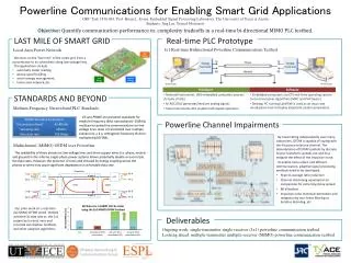
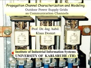
History of PLC and Motivation of Thesis • What is PLC • PLC – Powerline Communications • Using powerline as transmission medium for data communication • History of PLC • From high voltage (HV) low voltage (LV) • Low data rate high data rate • Control application multimedia data applications • Motivation • Cheap “the last mile” solution • However, worse channel than other wired network • Channel characterization reliable communications
PLC Technologies • Three network levels • High voltage (110–380 kV) • Medium voltage (10–30 kV) • Low voltage (230/400 V, in the USA 110 V) (my thesis range) • Efficient coupling • Inductive coupling • Conductive coupling • Modulation and error correction • OFDM, DMT • CDMA • FEC
EMC Issues • EMC --Electromagnetic compatibility • The ability of a device or system to function satisfactorily in its electromagnetic environment without introducing intolerable electromagnetic disturbances in the form of interferences to any other system in that environment, even to itself.
International National Regional Standardizations • PLC standardization bodies
Attenuation constant Propagation constant phase constant Characteristic impedance Transmission Line Theory • A piece of mains cable can be modeled as following figure R : resistance . L : inductance. G : conductance C : capacitance
Channel Measurement Setup • Equipment: • Network Analyzer (NA) • Coupling Circuit • Coupling circuit • Conductive coupling • High pass filter • Galvanic isolation • Over Voltage protection
Cable transversal • Rapid fluctuation caused by impedance mismatch • Maximum of 4 dB attenuation difference @ 100 MHz PLC Cable Measurements
PLC Channel Measurements • Scenario 1: Internet access and distribution • Scenario 2: Home networking Scenario 1: Network topology is known, or easy to estimate. Channel is simple, and has few multipath components Scenario 2: Network topology is unknown or it is hard to define. Channel acts as black box. A lot of multipath components
Frequency Domain Time Domain Channel Responses Scenario 1 Scenario 2
PLC Channel Modeling • According to PLC channel multipath phenomenon, channel can be modeled as:
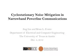
PLC Noise • Noise Classification: • Colored background noise • Narrowband noise • Periodic impulsive noise, asynchronous to the main frequency • Periodic impulsive noise, noise, synchronous to the main frequency • Asynchronous impulsive noise • Our concentration • Colored background noise • Asynchronous impulsive noise
Noise Measurement setup • Equipment: • Oscilloscope • Spectrum Analyzer • Coupler
Colored Background Noise • Quasi-Static behavior • Statistic information is extracted in table • Can be modeled as:
Random Impulsive Noise • Caused by frequency bursts generated by electrical devices connected to the powerline. • Statistic information is extracted
NEXT Formation FEXT Formation Other Disturbance • NEXT (Near End crosstalk) • FEXT (Far End crosstalk).
DMT Technology • Discrete Multi-tone Modulation (DMT) • Advantages: • Multicarrier technology – combat frequency selective fading • Dynamic bit loading based on SNR – efficient spectrum utilization • High channel capacity
DMT Based PLC Modem Design • Simulation environment: • MATLAB SimuLink • MATLAB DSP Blockset Simulated channel response • Expected result • Bit Error Rate (BER)
Modem performance PLC vs AWGN Simulation and Performance Optimized bit loading algorithm Signal spectrum before PLC channel Signal spectrum after PLC channel
Publications • More information can be found in my publications: • “Channel modeling and modem design for broadband power line communications”, Proceeding of ISPLC 2004, April, Spain • “Broadband characterization of indoor powerline channel”, Proceeding of ISPLC 2004, April, Spain • “Broadband Characterization of Indoor Powerline Channel and Its Capacity Consideration”, Proceeding of ICC 2005, May, Korea
Any Questions? Thank You!