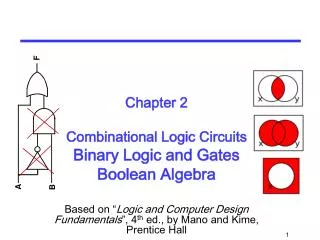
Binary Logic and Gates
Binary Logic and Gates. COE 202 Digital Logic Design Dr. Aiman El-Maleh College of Computer Sciences and Engineering King Fahd University of Petroleum and Minerals. Outline. Introduction Elements of Boolean Algebra (Binary Logic) Logic Gates & Logic Operations Boolean Algebra

Binary Logic and Gates
E N D
Presentation Transcript
Binary Logic and Gates COE 202 Digital Logic Design Dr. Aiman El-Maleh College of Computer Sciences and Engineering King Fahd University of Petroleum and Minerals
Outline • Introduction • Elements of Boolean Algebra (Binary Logic) • Logic Gates & Logic Operations • Boolean Algebra • Basic Identities of Boolean Algebra • Duality Principle • Operator Precedence • Properties of Boolean Algebra • Algebraic Manipulation
Introduction • Our objective is to learn how to design digital circuits. • These circuits use binary systems. • Signals in such binary systems may represent only one of 2 possible values 0 or 1. • Physically, these signals are electrical voltage signals • These signals may assume either a high or a Low voltage value. • The Highvoltage value typically equals the voltage of the power supply (e.g. 5 volts or 3.3 volts), and the Low voltage value is typically 0 volts (or Ground). • When a signal is at the High voltage value, we say that the signal has a Logic 1 value. • When a signal is at the Low voltage value, we say that the signal has a Logic 0 value.
Digital Circuits • The physical value of a signal is the actual voltage value it carries, while its Logic value is either 1 (High) or 0 (Low). • Digital circuits process (or manipulate) input binary signals and produce the required output binary signals.
Digital Circuits • Generally, the circuit will have a number of input signals (say n of them) as x1, x2, up to xn, and a number of output signals (say m ) Z1, Z2, up to Zm. • The value assumed by the ith output signal Zi depends on the values of the input signals x1, x2, up to xn. • In other words, we can say that Zi is a function of the n input signals x1, x2, up to xn. Or we can write: Zi= Fi(x1, x2, ……, xn ) for i = 1, 2, 3, ….m • The m output functions (Fi) are functions of binarysignals and each produces a single binary output signal. • Thus, these functions are binary functions and require binary logic algebra for their derivation and manipulation.
Boolean Algebra • This binary system algebra is commonly referred to as Boolean Algebra after the mathematician George Boole. • The functions are known as Boolean functions while the binary signals are represented by Boolean variables. • To be able to design a digital circuit, we must learn how to derive the Boolean function implemented by this circuit. • Systems manipulating Binary Logic Signals are commonly referred to as Binary Logic systems. • Digital circuits implementing a particular Binary (Boolean) function are commonly known as Logic Circuits.
Elements of Boolean Algebra (Binary Logic) • As in standard algebra, Boolean algebra has 3 main elements: • 1. Constants, • 2. Variables, and • 3. Operators. • Logically • Constant Values are either 0 or 1Binary Variables ∈{ 0, 1} • 3 Possible Operators: The AND operator, the OR operator, and the NOT operator.
Elements of Boolean Algebra (Binary Logic) • Physically • Constants ⇒ • Power Supply Voltage (Logic 1) • Ground Voltage (Logic 0) • Variables ⇒ Signals (High = 1, Low = 0) • Operators ⇒ Electronic Devices (Logic Gates) • 1. AND - Gate • 2. OR - Gate • 3. NOT - Gate (Inverter)
Logic Gates & Logic Operations The AND Operation • If X and Y are two binary variables, the result of the operation X AND Y is 1 if and only if both X = 1 and Y = 1, and is 0 otherwise. • In Boolean expressions, the AND operation is represented either by a “dot” or by the absence of an operator. Thus, X AND Y is written as X.Y or just XY.
Logic Gates & Logic Operations The AND Operation • The electronic device which performs the AND operation is called the AND gate. • Symbols of 2-input and 3-input AND gates:
Logic Gates & Logic Operations The OR Operation • If X and Y are two binary variables, the result of the operation X AND Y is 1 if and only if either X = 1 or Y = 1, and is 0 otherwise. • In Boolean expressions, the AND operation is represented either by a “plus” sign. Thus, X OR Y is written as X + Y. • The electronic device which performs the OR operation is called the OR gate.
Logic Gates & Logic Operations The NOT Operation • NOT is a “unary” operator. • IF Z=NOT X, then the value of Z is the complement of the value of X. If X = 0 then Z = 1, and if X = 1 then Z =0. • In Boolean expressions, the NOT operation is represented by either a bar on top of the variable (e.g. Z= ) or a prime (e.g. Z = X' ). • The electronic device which performs the NOT operation is called the NOT gate, or simply INVERTER.
Logic Circuits and Boolean Expressions • A Boolean expression (or a Boolean function) is a combination of Boolean variables, AND-operators, OR-operators, and NOT operators. • Boolean Expressions (Functions) are fully defined by their truth tables. • Each Boolean function (expression) can be implemented by a digital logic circuit which consists of logic gates. • Variables of the function correspond to signals in the logic circuit, • Operators of the function are converted into corresponding logic gates in the logic circuit.
Logic Circuits and Boolean Expressions • Example: Consider the function • Logic circuit diagram of :
Basic Identities of Boolean Algebra • AND Identities: • 0 . X = 0 • 1 . X = X • X . X = X • = 0
Basic Identities of Boolean Algebra • OR Identities: • 1 + X = 1 • 0 + X = X • X + X = X • = 1
Basic Identities of Boolean Algebra • AND Identities • OR Identities • Another Important Identity
Duality Principle • Given a Boolean expression, its dual is obtained by • replacing each 1 with a 0, each 0 with a 1, • each AND (.) with an OR (+), and each OR (+) with an AND(.). • The dual of an identity is also an identity. This is known as the duality principle. • It can be easily shown that the AND basic identities and the OR basic identities are duals.
Operator Precedence • Given the Boolean expression X.Y + W.Z the order of applying the operators will affect the final value of the expression.
Operator Precedence • For Boolean Algebra, the precedence rules for various operators are given below, in a decreasing order of priority:
Properties of Boolean Algebra • Properties of Boolean Algebra can be easily proved using truth tables. • The only difference between the dual of an expression and the complement of that expression is that • in the dual variables are not complemented while in the complement expression, all variables are complemented. • Using the Boolean Algebra properties, complex Boolean expressions can be manipulated into a simpler forms resulting in simpler logic circuit implementations. • Simpler expressions are generally implemented by simpler logic circuits which are both faster and less expensive.
Algebraic Manipulation • The objective here is to acquire some skills in manipulating Boolean expressions into simpler forms for more efficient implementations. • Properties of Boolean algebra will be utilized for this purpose. • Example: Prove that X + XY = X • Proof:X + XY = X.1 + XY =X.(1 + Y) = X.1 = X • Example: Prove that X + X`Y= X + Y • Proof: X + X`Y= (X+ X`) (X + Y)= 1.(X + Y)= X + Y • OR X + X`Y= X.1 + X`Y= X.(1+Y) + X`Y= X + XY + X`Y= X + (XY +X`Y)= X + Y(X +X`)= X + Y
Algebraic Manipulation • Example:Consensus Theorem XY + X`Z + YZ = XY + X`Z
Algebraic Manipulation • Example: Simplify the function
Algebraic Manipulation • Example: Simplify the function