Download
1 / 19
190 likes | 208 Views
Explore the upgrade of the Timing and Fast Control System for the LHCb experiment by PhD student Federico Alessio at CPPM, Marseille in June 2009.

E N D
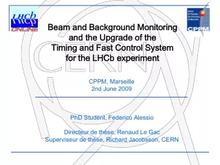
Beam and Background Monitoring and the Upgrade of the Timing and Fast Control System for the LHCb experiment CPPM, Marseille 2nd June 2009 PhD Student, Federico Alessio Directeur de thèse, Renaud Le Gac Superviseur de thèse, Richard Jacobsson, CERN
Large Hadron Collider @ CERN 7 TeV 7 TeV
First Beam 2008 CMS ATLAS LHCb ALICE
The challenge of a LHC experiment (online point of view) record as much data as possible with the highest precision ever • Beam & Background: • distinguish between real physics events and background due to physics events • monitor the beam in the experiment location • explain and predict possible bad behaviour of the beam (whenever possible protect the detector itself) • use of dedicated smaller detectors to define figure of merits • Physics Event Readout: • read out data from detector and trasfer to PC farm for offline analysis • distinguish interesting events from non-interesting events (trigger) • keep synchronicity of entire readout electronics and trasmit commands • mainly based on electronics boards, processors, computers, disks Federico Alessio
Beam and Background Monitoring @ LHCb • Complete study framework which involves: • Background monitoring • Beam Condition Monitor • Metal-foil based Radiation Monitoring System • Active Radiation Monitors • Beam Loss Scintillator • VELO/PUS • SPD • Beam monitoring • VELO/PUS (and indirectly also the others above) • Beam Phase and Intensity Monitor Federico Alessio
Beam Phase and Intensity Monitor Commonly known as BPIM, it is used to measure bunch-by-bunch the phase and the intensity of the proton beam with respect to the global clock gives a clear structure of the beam and the position of the orbit locally A full batch of 8 custom-made boards has been designed, produced, fully tested and FPGA processing written used with first beam in September 2008 The same board is used in ALICE for their trigger chain Federico Alessio
Beam Loss Scintillator • Monitor the injection phase: splashes from improper transfer from injection line to the LHC accelerator or beam instabilities at injection • Monitor continuous runs: real-time readout allows monitoring the status of the beam and possibly predict bad configuration of the LHC machine • Not meant to protect the LHCb experiment from beam accidents 2 scintillators + PMTs have been installed and tested with cosmics by RustemDzhelyadin • Proposal to use the Beam Phase and Intensity Monitor for the readout • only background monitor in LHCb which can detect fast losses • written processing in FPGA: running sums, histogramming, averages, alarm threshold • calibrated the full system corresponding to background levels of interests • developed control system common to BPIM and TFC system, possibility to archive data for offline analysis • full system will be validated during injection test 6-7 June and first (second) LHC beam Federico Alessio
LHCb Readout System Upgraded Detector VELO ECal HCal Muon RICH ST OT L0 Trigger L0 trigger FEElectronics FEElectronics FEElectronics FEElectronics FEElectronics FEElectronics FEElectronics Timing & Fast Control System LHC clock Readout Board Readout Board Readout Board Readout Board Readout Board Readout Board Readout Board Rethink/ Redraw/ Adapt/ Upgrade/ Replace Front-End MEP Request READOUT NETWORK Event building SWITCH SWITCH SWITCH SWITCH SWITCH SWITCH SWITCH SWITCH CPU CPU CPU CPU CPU CPU CPU CPU CPU CPU CPU CPU CPU CPU CPU CPU CPU CPU CPU CPU CPU CPU CPU CPU STORAGE CPU CPU CPU CPU HLT farm MON farm Federico Alessio
Work to do (in order to satify requirements) • Need to define protocols. • Very likely the readout link FE-ROB and the protocol will be based on CERN-GigaBitTransceiver (GBT) • Need to define buffer sizes and truncation scheme to be compliant with the worst scenario possible (big consecutive events which could overflow memories). • Need to fully control the phase of the recovered clock at the FE. • Necessary reproducibility of the clock phase each time the system is switched off/on • The jitter of the reconstructed clock must be very small (< 10ps RMS). • Need to control the rate in order to allow a “staged” installation • Partitioning as a crucial aspect for parallel stand-alone tests and sub-detectors development (test-bench support) Federico Alessio
S-TFC Architecture (i.e. the new s-heartbeat of the LHCb experiment) Federico Alessio
Simulation Full simulation framework to study buffer occupancies, memories sizes, latency, configuration and logical blocks Federico Alessio
Achievements and plans • Two main topics: • BPIM and BLS inserted in the framework of a larger background study in LHCb and LHC and framework monitoring of the beam behavior during shifts and continuous run • Boards developed, tested and installed • Ready to be used during LHC runs • Publications in preparation with LHC real-time results • the Upgrade of the Timing and Fast Control system in the framework of the LHCb Upgrade • LHCb Upgrade plans are well ahead • TFC system to be ready well before any other to allow development and R&D • First prototype will be developed with help of CPPM for validation of protocols, link transmission and FPGA processing • LHCb public note: • F. Alessio, R. Jacobsson, Z. Guzik: “Timing and Fast Control and Readout Electronics Aspects of the LHCb Upgrade”, LHCb-2008-072 • Presented at 16th IEEE-TNS Real Time Conference in Beijing, China: • F. Alessio, R. Jacobsson, Z.Guzik: “A 40 MHz Trigger-free Readout Architecture for the LHCb experiment”, submitted to TNS Merci! Federico Alessio
Backup Merci! Federico Alessio
Architectures, Old vs New LHC LHC CLOCK CLOCK DATA DATA DATA DATA DATA TRIGGER TRIGGER EVENT REQUESTS EVENT REQUESTS ECS ECS L0 L0 TFC TFC TFC DATA BANK TFC DATA BANK TFC TFC THROTTLE THROTTLE TFC TFC FE FE ROB ROB FARM FARM S-LHC CLOCK EVENT REQUESTS S-ECS S-TFC TFC DATA BANK TFC, THROTTLE TFC, DATA, ECS S-FE S-ROB S-FARM • No L0-trigger • Point-to-point bidirectional high-speed optical links • Same technology and protocol type for readout, TFC and throttle • Reducing number of links to FE by relaying ECS and TFC information via ROB Federico Alessio
Implications for Front-End The S-FE records and transmits data @ 40 MHz, via optical link @ 4.8 Gb/s (3.2 Gb/s data) It is necessary that Zero Suppression is performed in rad-hard FE Asynchronous data transfer • Data has to be tagged with identifiers • in header • Realigned in Readout Boards Courtesy Ken Wyllie, LHCb S-FE logical scheme NZS data, event size is 400kB@40MHz = ~16TB/s!! Federico Alessio
Timing and Fast Control (1) • Readout system requires timing, synchronization and various synchronous and asynchronous commands • Receive, distribute and align LHC clock and revolution frequency to readout electronics • Transmit synchronous reset commands, calibration sequences and control the latency of commands • Back-pressure mechanism from S-ROB to handle network congestion • 1. Effectively, throttle the readout rate • 2. Possibly implementing an “intelligent” throttle mechanism, capable of distinguish interesting physics events locally in each S-ROB Federico Alessio
Timing and Fast Control (2) • Farm has to grow in size, speed and bandwidth • Destination Control for the event packets in order to let the S-ROBs know where to send the event (to which IP address) • Request Mechanism (EVENT REQUESTS) to let the destination controller in the TFC system know if a node is available or not. The definition of such a readout scheme is a “push protocol with a passive pull” • A data bank has to contain info about the identity of an event and trigger source information. This info is added to each event (TFC DATA BANK) • New TFC system (prototype of S-TFC) has to be ready well before the rest of the electronics in order to allow development and testing, and validate conformity with the overall specs Federico Alessio
S-TFC Protocols • S-TFC Master S-TFC Interface link • TFC control fully synchronous 60bits@40MHz 2.4 Gb/s (max 75 bits@ 40 MHz 3.0 Gb/s) • Reed Solomon-encoding used on TFC links for maximum reliability (header ~16 bits) (ref. CERN-GBT) • Asynchronous data TFC info must carry Event ID • Throttle(“trigger”) protocol • 1. Must be synchronous (currently asynchronous) • Protocol will require alignment • TFC control protocol incorporated on link between S-FE and S-ROB (i.e. CERN GBT) • S-TFC Interface S-ROB • Copper or backplane technology (In practice 20 HI-CAT bidirectional links) • TFC synchronous control protocol same as S-TFC Master S-TFC Interface • One GX transmitter with external transmitter 20x-fan-out (PHYs - electrical) • Throttle(“trigger”) protocol using 20x SERDES interfaces <1.6 Gb/s Federico Alessio
Reaching the requirements: phase control • Use of commercial electronics: • Clock fully recovered from data transmission (lock-to-data mode) • Phase adjusted via register on PLL • Jitter mostly due to transmission over fibres, could be minimized at sending side 1. Use commercial or custom-made Word-Aligner output 2. Scan the phase of clock within “eye diagram” Still investigating feasibility and fine precision Federico Alessio