Download

1 / 29
990 likes | 4.93k Views
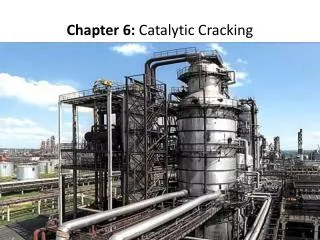
Fluid Catalytic Cracking (FCC). Quak Foo, Lee Chemical and Biological Engineering The University of British Columbia. Outline. What is FCC? Why use circulating Fluidized Bed Reactor in FCC? Operating Characteristics Description of the Process Heat Balance Pressure Balance Conclusions.

E N D
Fluid Catalytic Cracking(FCC) Quak Foo, Lee Chemical and Biological Engineering The University of British Columbia
Outline • What is FCC? • Why use circulating Fluidized Bed Reactor in FCC? • Operating Characteristics • Description of the Process • Heat Balance • Pressure Balance • Conclusions
What is FCC? • Primary conversion process in petroleum refinery. • The unit which utilizes a micro-spherodial catalyst (zeolitic catalyst) which fluidizes when properly aerated. • The purpose is to convert high-boiling petroleum fractions (gas oil) to high-value, high-octane gasoline and heating oil.
Why use Circulating Fluidized Bed in FCC? • Compared with Fixed Bed, Fluidized Bed • CFB – fast fluidization regime • CFB good for catalyst size < 0.2 mm • Excellent in: • Gas-solid effective contact • Catalyst effectiveness • Catalyst internal temperature control • Catalyst regeneration
Operating Characteristics • Particle Diameter = 150 m • Geldart Classification = A • Temperature = 650 0C • Pressure = 100 kPa • Superficial gas velocity = 10 m/s • Bed depth = 0.85 m • Fresh feed flow rate = 300,000 kg/hr • Catalyst to oil ratio = 4.8
Description of the Process • Reactor • Riser • Cyclones • Stripper • Regenerator • Standpipe and Slide Valve
Reactor Performance • Feed oil enters the riser near the base • Contacts the incoming regenerated catalyst • Cracking reactions occur in the vapor phase • Expanded volume of vapors lift the catalyst and vaporized oil rises • Fast reaction, few seconds of contact time
Riser • Dimensions • Diameter: 1.2 m (4 ft) • Height : 36.6 m (120 ft) • Plug flow with minimum back-mixing • Steam is used to atomize the feed • Increases the availability of feed • Outlet vapor velocity: 18 m/s (60 ft/sec) • Hydrocarbon residence time: 2 seconds
Cyclones • Located at the end of riser to separate the bulk of the catalyst from the vapor • Use a deflector device to turn catalyst direction downward • Two-stage cyclones • To separate the remaining of the catalyst • Return the catalyst to the stripper through the diplegs • The product vapors exit the cyclones and flow to the main fractionator column
Cyclones Riser Stripping Bed
Stripping Section • The spent catalysts falls into the stripper • Valuable hydrocarbons are absorbed within the catalyst bed • Stripping steam, at a rate of 4 kg per 1000 kg of circulating catalyst, is used to strip the hydrocarbons from the catalyst • The catalyst level provides the pressure head which allows the catalyst to flow into the regenerator
Inside Stripping Section Catalyst Level Steam Reactor Riser Reactor Stripper
Regenerator • Two functions: • Restores catalyst activity • Supplies heat to crack the feed • Air is the source of oxygen for the combustion of coke • The air blower with 1m/s (3 ft/s) air velocity to maintain the catalyst bed in a fluidized state • 14 kPa (2 psi) pressure drop in air distributors to ensure positive air flow through all nozzles
Inside Regenerator Catalyst (high carbon) Low Oxygen Dense Phase Bed Catalyst Air Catalyst (low carbon) High Oxygen
Standpipe & Slide Valve • Standpipe provides the necessary pressure head needed to circulate the catalyst around the unit • The catalyst density in standpipe is 642 kg/m3 (40 lbs/ft3) • Slide valve is used to regulate the flow rate of the regenerated catalyst to the riser • Slide valve function is to supply enough catalyst to heat the feed and achieve the desired reactor temperature
Heat Balance • A catalyst cracker continually adjusts itself to stay in heat balance. • The reactor and regenerator heat flows must be equal. • Heat balance performed around • the reactor • the stripper-regenerator • Use to calculate catalyst circulation rate and catalyst-to-oil ratio • overall heat balance
Heat Balance • The unit produces and burns enough coke to provide energy to: • Increase the temperature of the fresh feed, recycle, and atomizing steam from their preheated states to the reactor temperature. • Provide the endothermic heat of cracking. • Increase the temperature of the combustion air from the blower discharge temperature to the regenerator flue gas temperature. • Make up for heat losses from the reactor and regenerator to surroundings. • Provide for heat sinks, such as stripping steam and catalyst cooling.
FCC Heat Balance Regenerator Reactor Flue gas Spent Catalyst Products Heat of Coke Combustion Heat Losses Heat losses Heat of Reaction Recycle Regenerated Catalyst Fresh Feed Regeneration Air Feed Preheater
FCC Heat Balance Regenerator Reactor Flue gas Spent Catalyst Products Heat of Coke Combustion Heat Losses Heat losses Heat of Reaction Recycle Regenerated Catalyst Fresh Feed Regeneration Air Feed Preheater
Heat Balance Around Stripper-Regenerator • Heat to raise air from the blower discharge temperature to the regenerator dense phase temperature. (108 106 Btu/hr) • Heat to desorb the coke from the spent catalyst. (39.5 106 Btu/hr) • Heat to raise the temperature of the stripping steam to the reactor temperature. (4.4 106 Btu/hr) • Heat to raise the coke on the catalyst from the reactor T to the regenerator dense phase T. (3.7 106 Btu/hr)
Heat BalanceAround Stripper-Regenerator • Heat to raise the coke products from the regenerator dense temperature to flue gas temperature. (2.17 106 Btu/hr) • Heat to compensate for regenerator heat losses. ( 19.3 106 Btu/hr) • Heat to raise the spent catalyst from the reactor temperature to the regenerator dense phase. (305.5 106 Btu/hr)
Reactor Heat Balance • Hot-regenerated catalyst supplies the bulk of the heat required to vaporize the liquid feed • To provide the overall endothermic heat of cracking • To raise the temperature of dispersion steam and inert gases to the reactor temperature
Reactor Heat Balance • Heat into the reactor • Regenerated catalyst = 1186 106 Btu/hr • Fresh feed = 267 106 Btu/hr • Atomizing steam = 12 106 Btu/hr • Heat of absorption = 35 106 Btu/hr • Total heat in = 1500 106 Btu/hr
Reactor Heat Balance • Heat out of the reactor • Spent catalyst = 880 106 Btu/hr • To vaporize feed = 513 106 Btu/hr • Heat content of steam = 15 106 Btu/hr • Loss to surroundings = 6 106 Btu/hr • Heat of reaction = ? • Total heat out = 1414 106 Btu/hr + Heat of reaction
Reaction Heat Balance • Calculation of Heat of Reaction • Total heat out = Total heat in • Total heat in = 1500 106 Btu/hr • Total heat out = 1414 106 Btu/hr + Heat of reaction • Therefore, Overall Endothermic Heat of Reaction = 86 106 Btu/hr
Pressure Balance • Deals with the hydraulics of catalyst circulation in the reactor and regenerator circuit. • The incremental capacity come from increased catalyst circulation or from altering the differential pressure between reactor-regenerator.
Pressure Balance Results • In spent catalyst standpipe: • Pressure buildup = 27 kPa (4 psi) • Catalyst density = 658 kg/m3 • Optimum pressure to circulate more catalyst • In regenerated catalyst standpipe: • Pressure buildup = 55 kPa (8 psi) • Catalyst density = 642 kg/m3
Conclusions • Circulating Fluidized Bed is used in FCC unit. • Stripping steam of 4 kg per 1000 kg circulating catalyst is required. • Overall endothermic Heat of Reaction is 86 MBtu/hr. • Pressure buildup in spent catalyst standpipe is 27 kPa (4 psi). • Pressure buildup in regenerated catalyst standpipe is 55 kPa (8 psi).