Download
1 / 23
230 likes | 397 Views
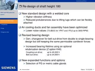
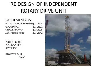
RE DESIGN OF INDEPENDENT ROTARY DRIVE UNIT.

E N D
RE DESIGN OF INDEPENDENT ROTARY DRIVE UNIT BATCH MEMBERS: P.GURUCHANDRANATHAN (07ME14) G.KUMANAN (07ME21) S.RAJESHKUMAR (07ME35) J.SATHISHKUMAR (07ME42) PROJECT GUIDE: S.S.NIVAS.M.E, ASST PROF PROJECT VENUE: ONGC
ABSTRACT • The present IRD unit is using gear coupling and chain coupling which seems to be ineffective & have short life time. • So we are proposing to use clutch mechanism instead of gear coupling in order to increase its efficiency & life span.
INTRODUCTION • The independent rotary drive system is used to dig the earth surface and collect the oil & gas which is avail in nature. • It consists of a drive to the rotary table by an independent motor through two speed transmission. • By installing the system, the drive to the rotary table from the draw works is eliminated. • An emergency sprocket is available in this system which gives a provision to use draw works drive in case of emergencies for a temporary failure or a redesign work.
COMPONENTS OF IRD UNIT GEAR COUPLING GEAR CHAIN COUPLING MOTOR ROTARY TABLE CLUTCH BRAKE
PROBLEM DESCRIPTION • At very high speeds (1000 rpm), the conventionally used gear coupling in IRD unit gets damaged very often. • In order to overcome this, we are going to redesign the coupling unit.
SPECIFICATION INPUT SPEED : 1240 rpm OUTPUT SPEED : 566-1240 rpm INPUT HORSE POWER : 600-1000 ihp INPUT SHAFT DIAMETER : 3.940 Inches OUTPUT SHAFT DIAMETER : 3.940 Inches GEAR RATIO : 1:1.128
METHODOLOGY • We can modify the gear coupling unit in two methods 1.Flange coupling. 2.Planetary gear mechanism. • By adopting these two methods the life of the coupling unit is increased compared to the existing gear coupling methods. • Of the two methods, the planetary gear mechanism is noisy in operation. • So we preferred implement of flange coupling
PLANNING • Study about planetary gear mechanism and flange coupling methodology. • Analysing the two methods. • Selection of the best among those two methods. • Implementation and Adoptation in the industrial applications.
INPUT SPECIFICATION: N=1240rpm P=1000HP 1HP=736W 1W=1NM/sec P=736x103W P=736KW DESIGN CALCULATION: P=(2πNT)/60 736=(2×π×1240×T)/60 T =5667969.586Nmm
DESIGN OF SHAFT: After analysing the various material, we are concluded the material for shaft as c45 from psg data book page no 1.9 τ=65N/mm2 σ=150N/mm2 we know that τ=π/16xτxd3 where,τ is the allowable shear strength for shaft material, we can calculate the shaft diameter 5667.96 x103 =π/16x65xd3 d=76.29 = 80 mm(approximately) Based on the observation made in the unit, it is cleared, we have to select more than 100mm diameter.
Because,the existing shaft dia is equal to 100mm. By referring Indian standard (IS 3688-1977) we will select d=122mm DESIGN OF VARIOUS PARAMETERS: τf =0.5d where, τf =thickness of flange d=shaft dia τf =61mm L=1.5d L=length of hub L=183mm D=2d
D=outer dia of hub D=2X122 D=244mm D1 =3d D1 =Pitch Circle dia D1 =366mm D2 =4d D2 =outside dia of flange D2 =488mm Number of bolts,n=4 for “d” up to 100mm
DESIGN OF HUB: we selected the hub material is plain carbon steel Ʈ = 40 N/MM2 σ = 80 N/MM2 T = 5667969.586 NMM T = π/16 X Ʈ h X [ D4 - d4/ D] D = outside diameter of hub d = shaft diameter of hub Ʈ h = 2.119 N/MM2 Induced shear stress of hub is less than 40 N/MM2 The design for the hub is safe
DESIGN OF KEY : From PSG data book page no 5.16 b = 22mm h = 14mm b = width of the key h = thickness of the key L = l = length of key = 120mm • Check for shearing: T = l X b X Ʈ k X d/2 5667969.586 = Ʈ k X 120 X 22 X 80/2 Ʈ k = 23.07 N/MM2 Induced shear stress of key is higher than the permissible stresses. The design for key is not safe
(b) CHECK FOR CRUSHING: T = σc X l X h/2 X d/2 h = thickness of key d = shaft diameter of key l = length of key 5667969.586 = σc X 120 X 14/2 X 80/2 σc = 72.535 N/MM2 Induced crushing stress of key is higher than the permissible stresses. The design for key is not safe.
To select the material c45 for the key because, it has the shear value greater than the calculated one that is τ=65n/mm2 b=25mm h=14mm Check for shearing: T = l x b x τx d/2 5667969.586 = 183 x 25 x τ x 122/2 τ = 20.3 N/MM2 Check for crushing: T = σcx l x h/2 x d/2 5667969.586 = σc x 183 x 14/2 x 122/2 σc = 72.535 N/MM2 b=28mm h=16mm
Check for shearing: τ = 18.13 N/MM2 Check for crushing: σc = 63.46 N/MM2 b=32mm h=18mm Check for shearing: τ = 15.86 N/mm2 Induced shear stress of key is less than the permissible stresses. The design for key is safe Check for crushing: σc = 56.41 N/mm2 Induced crushing stress of key is less than the permissible stresses. The design for key is safe.
DESIGN OF FLANGE: T=τхtfxπD2 /2 tf = Thickness of flange D=Outer diameter τ=1.515N/mm2 Induced shear stress of flange is less than the permissible stresses. The design for the flange is safe.
DESIGN OF BOLT: To select the bolt material is c45 τ=65N/mm2 σ=150N/mm2 T=τXnxdb2 xπ/4xD1 /2 where, db =dia of bolt n=num of bolt D1=pitch circle dia of bolts n=4 and db =13mm increase the bolt,so n=8 and db =9mm n=10 and db =8mm n=12 and db =7mm
Check for crushing: τ=σxnxdbxtf XD1 /2 Where, db =dia of bolt tf =thickness of flange Where, n=4 and d=12 σ=10.57N/mm2 n=8 and d=9 σ=7.05N/ mm2 n=10 and d=8 σ=6.34N/ mm2 n=12 and d=7 σ=6.044N/ mm2 Induced crushing stress is less than permissible stress The design of the bolt is safe.