Download
1 / 23
230 likes | 270 Views
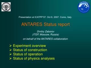
Detailed report on the ANTARES Project presented at the 10th International Conference on Astrophysics and Underground Physics in 2007. The text covers the detection principle, detector layout, optical modules, trigger system, data transmission, muon flux expectations, event reconstruction, atmospheric muon bundles, neutrino candidates, and calibration procedures.

E N D
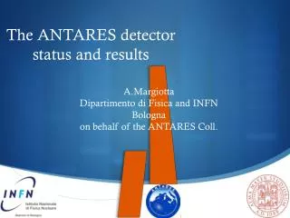
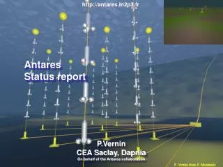
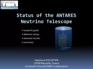
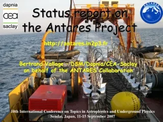
Status report on the Antares Project http://antares.in2p3.fr Bertrand Vallage – DSM/Dapnia/CEA-Saclay on behalf of the ANTARES Collaboration 10th International Conference on Topics in Astrophysics and Underground Physics Sendai, Japan, 11-15 September 2007
ANTARES shore station 40 km submarine cable 23 Institutes from7 European countries -2475m ANTARES collaboration and location 42°50’ N 6°10’E
Neutrino telescope: Detection principle 3D PMTarray p, a 107 atm 104 atm p m Cherenkov light from m gč 1-100 cosm g 43° Sea floor m interaction Reconstruction of m trajectory(~ n)from timing and position of PMT hits n
Detector layout Horizontal layout a storey 12 lines (900 PMTs) 25 storeys / line 3 PMTs/storey 14.5 m 350 m 40 km to shore 100 m Junction box ~70 m Readout cables Sea bed ~ -2500 m
Optical Module:10” PMTin17” glass sphere photon detection Local Control Module(in Ti container): Front-end ASIC, Clock, DAQ/SC,compass/roll/pitch Basic detection and calibration elements Optical Beaconwith blue LEDs: Timing calibration (4 per line) Hydrophone: acoustic positioning (5RX + 1RXTX/line)
L3 L2 L1 L5 L4 L8 L7 L6 L10 L9 L11 L12 9+1 lines in sea, 5 in operation (Sept. 2007) seismometer N 42°50’ N 6°10’E IL07 5 lines detector (since January 29th) Submarine cable to shore 100 m Junction box
Trigger and DAQ L0: PMT hit above 1/3 PE • PSD: • “SPE” • “Complex” • “Analog Ring Sampler” provides digitized integrated charge,time,timestamp: 6 Bytes • For high amplitude or high duration hits (~2%), possible to record full waveform: 272 Bytes Oscilloscope mode on double pulse • “ALL DATA TO SHORE” SCHEME: • each Optical Module provides at least 60 kHz of data ! (40K & biolum) • all data transmitted through multiplexed gigabit links: 200Mb-1Gb/s/line L1: coincidence at the storey level: 2 LO from 2 OMs out of 3 L2: - 3D trigger: 5 * (L1 or “large amplitude L0”), about 1 Hz - Min Bias, 40K, directional (GC), … : a few Hz + GRB alert (Swift)
bursts baseline Optical background Baseline: 40K decays + bacteria luminescence Bioluminescencebursts: Animal species which emit light by flashes, spontaneous or stimulated around the detector.
40K decays MC expectation: • 40K single rate about 40 kHz (10” PMT) • coincidence rate: 13 ± 4 Hz Measurement from data: g 14.5 ± 0.4 Hz Cherenkov g e- (b decay) 40K 40Ca Monitor relative PMT efficiencies Check timing within a storey
Connection Line 1 Connection Line 2 Connections Line3,4&5 Baseline variations 2005-2007 Instrumented Line date in 2005 Fraction of time above mean rate
k qc ℓ t0, , f, x, y, z m 3D Event reconstruction One of the very first “5 lines detector” events, Jan 29th 2007: 5 parameters fit by 2 minimization
up going down going Expected HE muon flux in ANTARES Zenith angle
up going down going First glimpse analysis Reconstructed Nadir angle after cut (straight lines): Very preliminary • Sample of reconstructed events (4.35 M from February to April) • Quality cut for upgoing tracks • No alignment used number of events Neutrino candidates cos
Event displays • Hits are plotted for each line: height(m) vs time(ns) • Characteristic pattern in function of zenith angle and point of closest approach between line and track: e.g for cda @ storey 13 (Z=0m) down going up going
Neutrino candidate (1) =55o
Neutrino candidate (2) =35o
Hydrophone AutonomousTransponder Calibration: detectorpositioning Acoustic distance measurement of hydrophones from fixed emitters on line anchors + autonomous transponders Line shape determined every 6 minutes from acoustic positioning + compass/roll/pitch slow control data hydrophones storey positions fit
"diagonal" • larger distance • less intensity • light scattering s = 2.6 ns s = 0.7 ns "horizontal" Tmeas - Texp [ns] Time calibration: LED beacons Line 1 Timing measurements performed once a week confirm the expected time resolution ~150 m Line2 ~70 m
Summary • 3D ANTARES detector operational with 5 lines; 4 extra lines in the sea waiting to be connected, 12 lines detector completed early 2008 • Several millions of down going events available to study detector behavior in various bioluminescence conditions • First underwater neutrino candidates reconstructed in the Mediterranean sea • Position and time calibration in progress to reach the nominal detector resolution • MC comparison ongoing, physics results expected soon