Download
1 / 19
190 likes | 400 Views
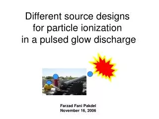
Different source designs for particle ionization in a pulsed glow discharge. Farzad Fani Pakdel November 16, 2006. Objective: Ionization of particles by pulsed glow discharge and study the ions with TOF-MS. Anode. Ar plasma. TOF detector. CsI particles. ions. Cathode. I +. Cs +.

E N D
Different source designs for particle ionization in a pulsed glow discharge Farzad Fani Pakdel November 16, 2006
Objective: Ionization of particles by pulsed glow discharge and study the ions with TOF-MS Anode Ar plasma TOF detector CsI particles ions Cathode I+ Cs+ High energy electrons Pre-peak Fragmentation Penning ionization Soft, ( CI ) After peak
Pulsed Glow Discharge Synchronized with TOF repeller f = 100 -1000 Hz Discharge pulse, Ionization Repeller of time of flight Will send a packet of ions to detector time 0 20 ms 0 - 300 ms
Experimental Setup GD TOF Solution of A salt (NaCl)
Discharge source: sleeve Argon flow cathode Insulator Anode ions TOF detector Argon flow carryingparticles skimmer Pressure gauge pump
Cesium Iodide (2.5mM) and Rubidium Iodide (7.5mM) Intensity (mv) I+ 85Rb+, 87Rb+ Cs+ Brass Ar2+ Mass / charge (amu)
Sodium Chloride (17mM) and Magnesium Nitrate (16mM) Repeller delay time = 56 msec Na+ Intensity (mv) Mg+ Cl+ H2O N2 O2 Ar + , ArH+ Mass / charge (amu)
Problems: -Can not increase the flow -Clogging at needle valve as a result -Particles pass very fast -Signal was not reproducible sleeve cathode Insulator Anode ions skimmer Corrosion (sputtering) Pressure gauge pump
Changing the anode design (anode C) + Increases the residence time for particles + Higher flows allowed (500, instead of 150 ml/min) -Reduces the ion transfer yield cathode Insulator Anode Cathode Anode
Comparing Anodes No particle Only argon A2 C2 B2 Signal intensity (mv) Ar = 40 ArH = 41 Cu = 63 20 40 60 80 100 Repeller delay time (ms)
Ionization of CsI particles Nebulized from 10mM CsI solution (Anode C) Max Cs+ signal at 58-60 ms Signal intensity (mv) Repeller delay time (ms)
Signal stability study (Cs) Repeller delay is fixed at 58 ms Integ time = 3s 2mM 0.5mM 0.1mM 1 mM Collection time (0-14min)
Argon only, through the back sleeve Max sputtered? Ar = 40 ArH = 41 Cu = 63 Signal intensity (mv) Penning ionization Repeller delay time (ms)
Ideal design! + Allows more residence time for particles + Higher flows allowed (500, instead of 150 ml/min) + Argon back flow interacts with particles and increases their residence time, enhances ionization (Penning) *no more reduced ion transfer yield Argon flow cathode Insulator Anode Cathode Anode
Ionization study by emission spectroscopy vacuum Anode Cathode (-) emission Particles detector Insulator Argon in
Laser ablation with anode C cathode Insulator Anode laser Cathode Anode
Laser Ablation Laser mirror Lenz
63Cu signal by time in successive spectrums (Transient mode) = 240 mass specs Laser on Intensity (mv) 240 sec 0 sec Time Power supply on