Download
1 / 58
580 likes | 732 Views
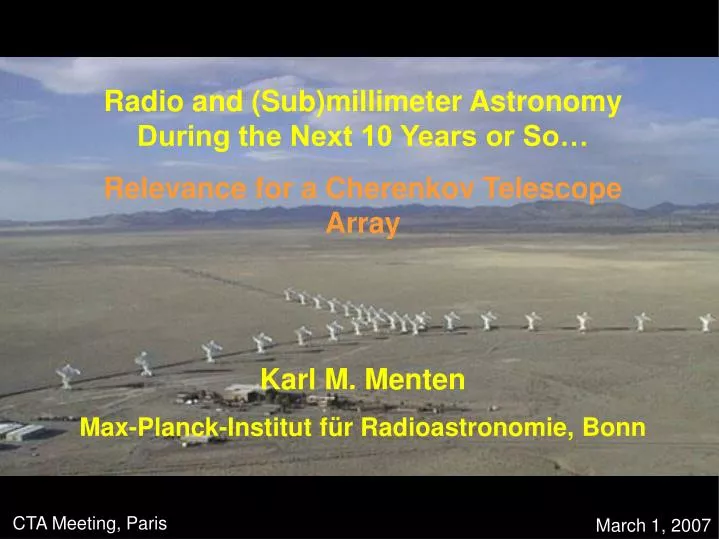
Radio and (Sub)millimeter Astronomy During the Next 10 Years or So… Relevance for a Cherenkov Telescope Array Karl M. Menten Max-Planck-Institut f ür Radioastronomie, Bonn. CTA Meeting, Paris. March 1, 2007. Radio Continuum Emission: non thermal (= synchrotron radiation)

E N D
Radio and (Sub)millimeter Astronomy During the Next 10 Years or So… Relevance for a Cherenkov Telescope Array Karl M. Menten Max-Planck-Institut für Radioastronomie, Bonn CTA Meeting, Paris March 1, 2007
Radio Continuum Emission: • non thermal (= synchrotron radiation) • general ISM, SNRs • AGN • PSRs • thermal (= Bremsstrahlung) • HII regions 10-23
Thermal emission can also be observed in spectral lines: Radio: 21 cm line of neutral hydrogen HI (1421 MHz) (Sub)mm: Rotational emission from CO: 115.5 GHz and multiples thereof
Our milky way across the electromagnetic spectrum HI CO 60 – 100 m 2 – 4 m
The 21-cm Neutral Hydrogen Line G a l a c t i c p l a n e All-sky map of emission in the 21-cm line Hartmann & Burton
1.2 m Columbia/CfA CO survey (Dame/Thaddeus et al.) Carbon monoxide (CO) emission [CO/H2] 10-4 [all other molecules/H2] << [CO/H2]
Millimeter Submillimeter COBE FIRAS 7 resolution Fixsen et al. 1994
Interstellar medium cartoon Galactic plane very hot low density gas * Dense cloud cores Supernova diffuse cloud Giant Molecular Cloud (GMC) new stars (IR sources)
Typical characteristics of GMCs: Mass = 104...106 M Distance to nearest GMC = 450 pc (Orion) Typical size = 5...100 pc Size on the sky of near GMCs = 5...dozens x full moon Average temperature (in cold parts) = 20...30 K Typical density = 102...106 molecules/cm3 Contain ca. 1% dust (by mass) Typical (estimated) life time = ~107 year Star formation efficiency = ~1%...10% Giant Molecular Clouds
Half-power beamwidth Full width at half maximum (FWHM) 1.22 /D
FWHM “Error beam” Response of a radio telescope to radiation Main beam B Full width at half maximum FWHM=1.22/D Error beam can pick up significant part of the signal, up to 50%
Effelsberg 100m IRAM 30m APEX 12m B = 22 @ 44 GHz B = 22 @ 112 GHz B = 22 @ 380 GHz 1.22 /D B = 4’ @ 4.0 GHz (Telescopes are not reproduced on same scale)
Our milky way across the electromagnetic spectrum HI CO rays Atomic Gas: H Molecular Gas: H2 60 – 100 m 2 – 4 m All interstellar matter
Empirical CO column density determination: • HE (~100 MeV – few GeV)-ray emissivity number of nucleons • CO emissivity WCO(K km s-1) -ray emissivity • N(cm-2) = XWCO or n(cm-3) = X/l WCO CO emission is always optically thick
The Galactic Center Region as seen by SCUBA at 850 m Pierce-Price et al. 2000 (Optically thin) (sub)millimeter continuum emission from interstellar dust is an excellent column density probe Problem: Weakness of emission. Need N > a few 1022 cm-2 to make large-scale mapping practical.
Single dish: = /D D Interferometer: = /B B Largest structure that can be imaged given by telescope diameter zero spacing problem
Interferometry • combine signals from two antennas separated by baseline vector b in a correlator; each sample is one “visibility” • each visibility is a value of the spatial coherence function V (b) at coordinates u and v • obtain sky brightness distribution by Fourier inversion: • Telescopes can be combined all over the world: Very Long Baseline Interferometry (VLBI) (sub)milliarcsecond resolution
ALMA snapshot 4.9 GHz/instantaneous sampling of a source at = 30 and hour-angle 0 /VLA/A configuration. Central hole More data points are filled in as the Earth rotates
The Very Large Array (VLA) • Built 1970’s, dedicated 1980 • 27 x 25m diameter antennas • Two-dimensional 3-armed array design • Four scaled configurations, maximum baselines 35, 10, 3.5, 1.0 Km. • Eight bands centered at .074, .327, 1.4, 4.6, 8.4, 15, 23, 45 GHz • 100 MHz total IF bandwidth per polarization • Full polarization in continuum modes. • Digital correlator provides up to 512 total channels – but only 16 at maximum bandwidth. VLA in D-configuration (1 km maximum baseline)
Single dish: = /D D Interferometer: = /B B Largest structure that can be imaged given by telescope diameter zero spacing problem
The Australia Telescope Compact Array Six 22m diameter antennas movable in E-W direction Most interesting for CTA: L- and S-band (1350 and 2700 MHz)
SNR RXJ713.7-3946 a.k.a. G347.3-0.5 HESS peak Radio void
ATCA 40” beam ROSAT Lazendic et al. 2004
Interferometer field of view = FWZP of unit telescope “Mosaicing”
1357 MHz 2495 MHz
ATCA NRAO VLA Sky Survey NVSS “officially” stops here
Aharonian et al. 2005 Brogan et al. 2005
J1640-465 March 2007 ASCA Source MOST 843 MHz B = ca. 2 arcmin Whiteoak & Green 1996 Aharonian et al. 2006 Funk et al. et al. 2007
High Fidelity Imaging Precise Imaging at 0.1” Resolution Routine Sub-mJy Continuum Sensitivity Routine mK Spectral Sensitivity Wideband Frequency Coverage Wide Field Imaging Mosaics Submillimeter Receiver System Full Polarization Capability System Flexibility (Total Power capability on ALL antennas) ALMA Science Requirements
Chajnantor SW from Cerro Chajnantor, 1994 May AUI/NRAO S. Radford
Complete Frequency Access Note: Band 1 (31.3-45 GHz) not shown
50 12-m antennas, at 5000 m altitude site Surface accuracy 25 m, 0.6” reference pointing in 9m/s wind, 2” absolute pointing all-sky Array configurations between 150m to ~15km 10 bands in 31-950 GHz + 183 GHz WVR. Initially: 86-119 GHz “3” 125-163 GHz “4” 211-275 GHz “6” 275-370 GHz “7” 385-500 GHz “8” 602-720 GHz “9” 8 GHz BW, dual polarization Interferometry, mosaics, & total-power observing Correlator: 4096 channels/IF (multi-IF), full Stokes Data rate: 6Mb/s average; peak 60Mb/s ALMA Specifications
Most extended: 150 m 10,000m ALMA – Extreme Configurations Most compact: Very small field of view: 20” FWHM at 300 GHz
The CTA will have an angular resolution of ca. 2 arcmin. • Most HESS sources are extended on 10’s of arcmin to ~1 degree scale • In radio and (sub)mm, want imaging capability that allows good fidelity multi-wavelength imaging that recovers these structures. • Radio: Interferometer multi- (at least 2-), long wavelengths • (Sub)mm: Single dish telescopes with spectral line receiver arrays
The APEX telescope • Built and operated by • Max-Planck-Institut fur Radioastronomie • Onsala Space Observatory • European Southern Observatory • on • Llano de Chajnantor (Chile) • Longitude: 67° 45’ 33.2” W • Latitude: 23° 00’ 20.7” S • Altitude: 5098.0 m • 12 m • = 200 m – 2 mm • 15 m rms surface accuracy • In opertaion since September 2005 • First facility instruments: • 345 GHz heterodyne RX • 295 element 870 m Large Apex Bolo- meter Camera (LABOCA) • http://www.mpifr-bonn.mpg.de/div/mm/apex/
To study larger-scale molecular cloud environments, degree-scale areas have to mapped. • CO lines are relatively strong. • Still: 1 deg2 40000 APEX beam areas • Advantages of array receivers: • Mapping speed • Mapping homogeneity (map lage areas with similar weather conditions/elevation) minimize calibration uncertainties.
Common sense requirements: Schuster et al. 2004 http://iram.fr/IRAMES/telescope/HERA/ • Important: • Uniform beams • Uniform TRX • and • TRX not “much” worse than TRX of state-of-the-art single pixel RX
Columbia/CfA 1m CO J = 1 0 (115 GHz)FWHM = 8.7 arcmin FWHMeff= 30 arcmin IRAM 30m CO J = 2 1 (231 GHz)HERA 9 x 11” Factor ~160 in resolution! Ungerechts & Thaddeus 1987 Schuster et al. 2004
Philipp et al. 2005 CHAMP+ Carbon Heterodyne Array of the MPIfR • 2 x 7 pixels • frequency range 602 – 720 and 790 – 950 simultaneously • beamsize 9" – 7" and 7" – 6" • IF band 4 – 8 GHz
Covered now by CHAMP+@APEX 7 450 m/7 350 m array Will be Covered by APEX 7 870 m/19 600 m array (to arrive in 2008) COBE FIRAS 7 resolution Fixsen et al. 1994
The APEX Galactic Plane survey • Image continuum emission from interstellar dust over -80° < l < +20° ; | b | < 1° • Instrumentation: LABOCA (Large APEX BOlometer CAmera) = 295 bolometers for observing at870 mm • APEX beam at 870 mm: • 18"=MSX pixels = Herschel at250 mm