Download
1 / 29
320 likes | 570 Views
Air and Ozone Sparging of TCE Using a Directionally Drilled Horizontal Well Site 86, Camp Lejeune. Mark Strong, P.E. CH2M HILL Christopher Bozzini , P.E. CH2M HILL Daniel Hood, NAVFAC Mid-Atlantic Bob Lowder, MCB Camp Lejeune EMD. Camp Lejeune Background.

E N D
Air and Ozone Sparging of TCE Using a Directionally Drilled Horizontal WellSite 86, Camp Lejeune Mark Strong, P.E. CH2M HILL Christopher Bozzini, P.E. CH2M HILL Daniel Hood, NAVFAC Mid-Atlantic Bob Lowder, MCB Camp Lejeune EMD
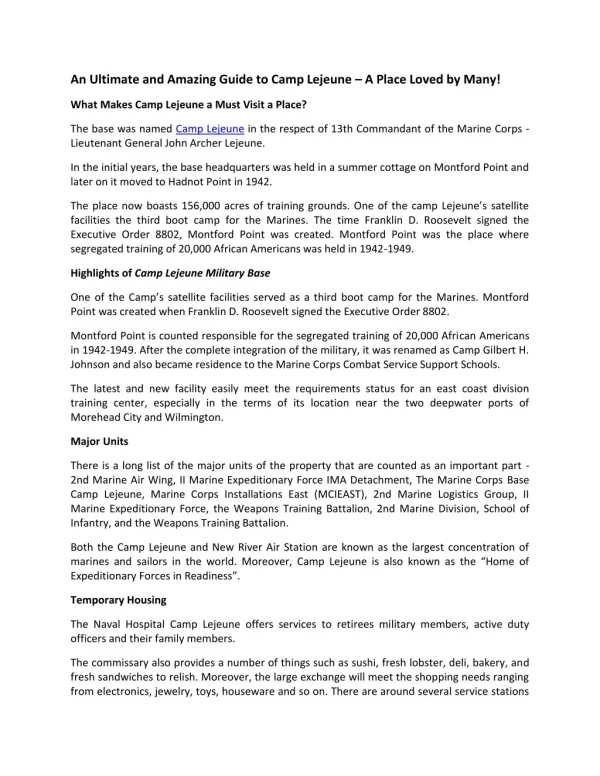
Camp Lejeune Background • Second largest U.S. Marine Corps Base in the Country • Camp Lejeune was established near the city of Jacksonville, N.C, in 1942. • Base covers 236 square miles • CERCLA site since 1989 • 22 Operable Units (OUs), 97 Sites.
Site Location and History • Site 86 is associated with three former waste oil ASTs, used during the 70s and 80s • Over the course of several investigations since 1992, the solvent plume migrated away from the source area and now extends several hundred feet off-site Bld. 25
Pilot Test Objectives • Prevent further migration of the TCE plume off-site • Evaluate air (and ozone) distribution using a horizontal well • Determine if ozone and/or air sparging can reduce TCE impacts to below regulatory standards within one year
Air Sparge ‘Screen” 4” SDR 11 HDPE Pipe 0.020 Inch Wide Slots 0.5% Open Area
Directional Sparge Well Layout Total Length of Drill = 950’ Total Slotted Length - 350’
Compressor and Ozone Generator Temporary Buildings (Connex Boxes)
Ozonia Generator (CFV-03, 60 ppd, air feed) Photo courtesy Ozonia North America
Schedule • Three Months of Air Sparging (120-140 cfm) • One Month of “Rebound” Monitoring • Six Months of Ozone Enhanced Air Sparging (~ 7000 ppmv) • Three Months of “Rebound” Monitoring (Recently Completed)
Ozone Injection Performance • Ozone production began in late July, 2005 • Intermittent operation from July to December • Mechanical issues: desiccant dryer and chiller • Total aggregate run time ~ 2-1/2 months (50% up time) • Total mass of ozone delivered ~ 3900 pounds
Average TCE ConcentrationsZone “A” Monitoring Wells (30-35’ Screen Depth)
Average TCE ConcentrationsZone “B” Monitoring Wells (40 - 45’ Screen Depth)
Average TCE ConcentrationsZone “C” Monitoring Wells (50 - 55’ Screen Depth)
Discussion • SVE was not conducted because of low permeability overburden; trace levels of TCE measured in shallow vapor during operation (ppbv) • Air was diverted horizontally by overburden; air bubbling was observed 300 feet from the well • Lateral propagation of air “fingering” was estimated to be 50 feet on either side of the well, as indicated by dissolved oxygen concentrations • Negligible increases in dissolved chloride from baseline levels
Conclusions • 90% average reduction of TCE within three months in wells with baseline TCE > 50 μg/L • 99% average reduction within one year in wells with baseline TCE > 50 μg/L • No significant rebound after three months (greater than 25 µg/L) • Distance of influence ~ 50 ft on both sides of the well (as indicated by DO measurements) • Possible contribution of ozone to TCE mass reduction inconclusive - low TCE concentrations and limited period of operation
Summary of Costs • $750K Total Budget • Horizontal Well, Compressed Air System, Container, Electrical ~ $250K • Ozone System and Container ~ $300K • Monitoring ~ $100K • O&M ~ $100K