Download
1 / 50
520 likes | 691 Views
802.11 Wireless LANs. Abhishek Karnik, Dr. Ratan Guha University Of Central Florida. OVERVIEW . Introduction 802.11 Basics 802.11e for QoS WEP . INTRODUCTION. In 1997 the IEEE adopted IEEE Std. 802.11-1997 Defines MAC and PHY layers for LAN and wireless connectivity.

E N D
802.11 Wireless LANs Abhishek Karnik, Dr. Ratan Guha University Of Central Florida
OVERVIEW • Introduction • 802.11 Basics • 802.11e for QoS • WEP
INTRODUCTION • In 1997 the IEEE adopted IEEE Std. 802.11-1997 • Defines MAC and PHY layers for LAN and wireless connectivity. • Facilitate ubiquitous communication and location independent • computing • 802.11b operates at 11Mbps in the 2.4 GHz ISM Band (‘99) • 802.11a operates at 54Mbps in the 5 GHz Band (’99) • 802.11g operates at 54Mbps in the 2.4 GHz Band (’02) • Increased deployment and popularity lead to introduction of QoS • 802.11e for QoS – Draft Supplement – Nov 2002
802.11 BASICS • Wireless LAN StationThe station (STA) is any device that contains the functionality of the 802.11 protocol, that being MAC, PHY, and a connection to the wireless media. Typically the 802.11 functions are implemented in the hardware and software of a network interface card (NIC). • Ex : PC , Handheld , AP (Access Point) • Basic Service Set (BSS) 802.11 defines the Basic Service Set (BSS) as the basic building block of an 802.11 wireless LAN. The BSS consists of a group of any number of stations.
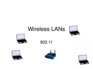
STA STA STA STA IBSS (Independent Basic Service Set – Ad-hoc Mode) peer-peer connections
Wired Backbone AP Infrastructure Basic Service Set
Wired Backbone AP AP ESS (Extended Service Set) BSS2 BSS1
Beacon TBTT PCF DCF Super Frame DCF - Distributed Coordinated Function (Contention Period - Ad-hoc Mode) PCF - Point Coordinated Function (Contention Free Period – Infrastructure BSS) Beacon - Management Frame Synchronization of Local timers Delivers protocol related parameters TBTT - Target Beacon Transition Time
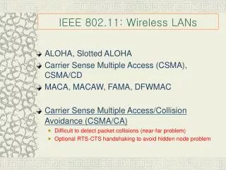
Distributed Coordinated Function (DCF) • Also known as the Contention Period • STAs form peer-peer connections. No central authority • First listen and then speak • Uses CSMA/CA (Carrier Sense Multiple Access with • Collision Avoidance) • ACK indicates successful delivery • Each node has one output buffer
Inter-Frame Spacing : DIFS - 34 µsec PIFS - 25 µsec ( Used in PCF ) SIFS - 16 µsec Slot Time - 9 µsec DIFS = SIFS + (2 * Slot Time) SIFS required for turn around of Tx to Rx and vice versa
CWA DIFS ACK DATAA ACKB DIFS SIFS Data Transmission from Node A to B • CW – Contention Window. Starts only after DIFS. • Random number ‘r’ picked form range ( 0-CW ) • CWmin minimum value of CW • CWmax maximum value the CW can grow to after collisions • ‘r’ can be decremented only in CW • CW doubles after every collision
CWA DIFS ACK DATAA ACKB DIFS SIFS • What if some node C wanted to send data while A was transmitting • data to B ? • What about during SIFS ? • What if after ACK, more than one say B,C,D,E nodes are waiting • to transmit data ?
Example : rA = 4 and rC = 6 DIFS ACK DATAA ACKB DATAC DIFS SIFS • What if rA and rC had both been picked as 4 ? • What if rA and rC has collided and DATAA length was 10 while • DATAC length were 15 ?
A Collision between nodes A and C DATAC ACK DATAA DIFS SIFS DIFS • Length (DATAA) = 10 Slot times • Length (DATAC) = 15 Slot times • CW after Collision 1 0 – 7 • CW after Collision 2 0 – 15 • CW after Collision 3 0 – 31 • CW after Collision 4 0 – 63
NAV – Network Allocation Vector STAA DATA ACK STAB STAC ACK SIFS DIFS DIFS NAVB and C
Hidden Node Problem and Exposed Node Problem STAC STAB STAA
RTS/CTS : • RTS (Request To Send) - (Approx 20 bytes) • CTS (Clear To Send) - (Approx 16 bytes) • Use of RTS/CTS is optional • Solves two problems : • Hidden Node Problem • Wastage of time due to collisions • Maximum MSDU is 2304 bytes
Preventing a collision at STAB RTS CTS C B A CTS CTS D
DIFS CW SIFS SIFS SIFS DIFS STAA RTS DATA STAB CTS ACK ACK NAV STAC STAD NAV New Node NAV
Point Coordinated Function (PCF) • Also known as the CFP (Contention Free Period) • Operation in an Infrastructure BSS • STAs communicate using central authority known as PC • (Point Coordinator) or AP (Access Point) • No Collisions take place • AP takes over medium after waiting a period of PIFS • Starts with issue of a Beacon
Beacon • Management Frame • Synchronization of Local timers • Delivers protocol related parameters • TBTT - Target Beacon Transition Time Beacon TBTT PCF DCF Super Frame
AP taking over the Wireless medium using PIFS PIFS DATA A B DIFS SIFS DIFS DIFS - 34 µsec PIFS - 25 µsec SIFS - 16 µsec Slot Time - 9 µsec B - Beacon
Operation in CFP CP CFP B D1 + Poll D2 + ACK + Poll CF_End U1 + ACK U1 + ACK SIFS
Admission Control • Purpose of having separate DCF and PCF • Different 802.11 Working groups • 802.11a (54Mpbs in 5GHz Band) • 802.11b (11 Mbps in 2.4 GHz Band) • 802.11c Wireless AP Bridge Operations • 802.11d Internationalization • 802.11e (QoS) • 802.11f Inter-vendor AP hand-offs • 802.11h Power control for 5Ghz region • 802.11g (54Mbps in 2.4 GHz Band) • 802.11i (Security)
802.11e for QoS • QoS (Quality of Service) • 802.11e for QoS – Draft Supplement – Nov 2002 • Introduction of new QoS mechanism for WLANs
HC PC ( Enhanced Station ) BSS (Basic Service Set) QBSS (Basic Service Set for QoS) PCF DCF HCCA EDCA
QoS Support Mechanisms of 802.11e : • EDCA : • Introduction of 4 Access Categories ( AC ) with 8 Traffic • Classes ( TC ) • MSDU are delivered through multiple back offs • within one station using AC specific parameters. • Each AC independently starts a back off after • detecting the channel being idle for AIFS • After waiting AIFS , each back off sets counter from • number drawn from interval [1,CW+1] • newCW [AC] >= ((oldCW[TC] + 1 ) * PF ) - 1
Prioritized Channel Access is realized with the QoS parameters per TC, which include : • AIFS[AC] • CWmin[AC] • PF[AC]
EDCA TC AC1 AC2 AC3 AC4 Virtual Collision
Access Category based Back-offs AIFS[AC3] AIFS[AC2] AIFS[AC1] AIFS[AC0] BackOff[AC3] + Frame BackOff[AC2] + Frame BackOff[AC1] + Frame ACK BackOff[AC0] + Frame
QoS Parameter Set Element Format CWmin[AC] CWmin[0]….CWmin[3] CWmax[AC] CWmax[0]….CWmax[3] Element ID AIFSN[AC] AIFSN[0]….AIFSN[3] TxOPLimit[AC] TxOP[0]….TxOP[3] AIFS [AC] = AIFSN [AC] * aSlotTime + SIFS
HCCA ( Hybrid Coordination Function Controlled Channel Access ) • Extends the EDCA access rules. • CP : TxOP • After AIFS + Back off • QoS Poll ; After PIFS • CFP : TxOP • Starting and duration specified by HC using • QoS Poll .
Hybrid Coordinator HC PIFS HCCA EDCA PIFS DATA A DATA AIFS SIFS AIFS
802.11e Operation in the CFP • Guaranteed channel access on successful registration • Each node will receive a TxOP by means of polls granted • to them by the HC • TxOP based on negotiated Traffic specification (TSPEC) and • observed node activity • TxOP is at least the size of one Maximum sized MSDU at the • PHY rate. • Access Point advertises polling list
Traffic Specification (TSPEC) Element ID (1) Length (1) TS info (2) Nominal size MSDU (2) Maximum MSDU size (2) Minimum Service Interval (4) Maximum Service Interval (4) Inactivity Interval (4) Minimum Data Rate (4) Mean Data Rate (4) Maximum Burst Size (4) Minimum PHY Rate (4) Peak Data Rate (2) Delay Bound (2) Surplus Bandwidth Allowed (2)
AIFS[AC] = AIFSN[AC] * aSlotTime + SIFS PIFS - 25 µsec ( Used in HCCA) SIFS - 16 µsec Slot Time - 9 µsec AIFS[0] = (2 * 9) + 16 = 34 µsec = DIFS AIFS[1] = (4 * 9) + 16 = 52 µsec (52 – 34) / 9 = 18/9 = 2 Slots AIFS[2] = (7 * 9) + 16 = 79 µsec (79 – 34) / 9 = 45/9 = 5 Slots
Back-off Algorithm : 802.11 : CWRANGE= [ 0 , 2 2+i – 1 ] 802.11e : newCW[AC] = [(oldCW[AC] + 1) * PF] - 1
WEP (Wired Equivalent Privacy) • Optional in WLANS • Uses the RC4 (Rivest Cipher 4) Stream Cipher generated with a 64bit/128 bit Key • Key composed of 24 bit IV (Initialization Vector) • Key = (24 Bit IV, 40 Bit WEP Key) = 64 Bits • Key = (24 Bit IV, 104 Bit WEP Key) = 128 Bits • Goal to provide authentication, confidentiality and data integrity • Secret Key is shared between communicators • The encrypted packet is generated with a bitwise exclusive OR (XOR) of the original packet and the RC4 stream. • 4-byte Integrity Check Value (ICV) is computed on the original packet and appended to the end which is also encrypted with the RC4 cipher stream. • Encryption done only between 802.11 stations.
Encrypted WEP Frame http://www-106.ibm.com/developerworks/security/library/s-wep/
Encryption / Decryption : • M – Original Data Frame • CRC-32 (c) applied to M to obtain c (M) • c (M) and M are concatenated to get Plain Text P = (M, c (M)) • WEP produces a Key-stream as a function 24 bit IV and 40-bit WEP Key • using RC4; equal to the length of P. • Key Stream and the Plaintext are XORed to produce the Cipher Text • The IV is transmitted in the clear (unencrypted) • The receiver uses the IV and the shared key to decrypt the message
Draw Backs of WEP: • A number of attacks can be used against WEP • Passive Attacks based on statistical analysis • Active Attacks based on known plain text • WEP relies on a Shared Key to ensure that packets are not • modified in transit. • There is no discussion on how these keys are distributed and • hence usually a single key is used which is shared amongst • all STA’s and the AP
All in a days work : • Shared Key is long lived – May last a week, month, • even a year or more • Consider a busy AP which constantly sends packets • of length 1500 bytes at 11Mbps • Since IV on 24 bits in length and Shared key is • unchanged, IV gets exhausted after • 2^24 * (1500 * 8) / (11 * 10^6) • = 18000 secs = 5 hours • Lucent wireless cards
PT Key CT CT Key PT • XOR : • 0 0 0 • 0 1 1 • 0 1 • 1 1 0 • XORing a Bit with itself gives 0
PASSIVE ATTACK Sender PT K CT 0 0 0 0 1 1 1 0 1 1 1 0 Receiver CT K PT 0 0 0 1 1 0 1 0 1 0 1 1
IV repeats generating K • Identical K used to encrypt MSG1 and MSG2 MSG1 K C ( MSG1 ) MSG2 K C ( MSG2 ) • Obtain C( MSG1) and C( MSG2) and XOR them • XORing causes Key Stream to cancel which yields • the XOR of MSG1 and MSG2 i.e. XOR of Plain Text packets • This XOR can now be used to apply Statistical Analysis
Example : MSG1 0 0 1 1 MSG2 1 0 1 1 MSG2 PT2 K CT2 1 0 1 0 1 1 1 0 1 1 1 0 MSG1 PT1 K CT1 0 0 0 0 1 1 1 0 1 1 1 0
CT1 XOR CT2 CT1 CT2 0 1 1 1 1 0 1 1 0 0 0 0 MSG1 XOR MSG2 MSG1 MSG2 0 1 1 0 0 0 1 1 0 1 1 0 Apply Statistical analysis on last three bits and educated guess on the rest
AP Wired Network xx Hi Attacker
Active Attack : • Attacker knows exact plain text for one encrypted packet • Use this knowledge to construct correct encrypted packet • Construct a new message , calculate CRC-32 and perform • bit flips on original encrypted packet to change the plaintext • to the new message.