LAN Technologies
170 likes | 333 Views
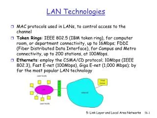
LAN Technologies. MAC protocols used in LANs, to control access to the channel Token Rings : IEEE 802.5 (IBM token ring), for computer room, or department connectivity, up to 16Mbps; FDDI (Fiber Distributed Data Interface), for Campus and Metro connectivity, up to 200 stations, at 100Mbps.

LAN Technologies
E N D
Presentation Transcript
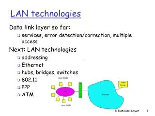
LAN Technologies • MAC protocols used in LANs, to control access to the channel • Token Rings: IEEE 802.5 (IBM token ring), for computer room, or department connectivity, up to 16Mbps; FDDI (Fiber Distributed Data Interface), for Campus and Metro connectivity, up to 200 stations, at 100Mbps. • Ethernets: employ the CSMA/CD protocol; 10Mbps (IEEE 802.3), Fast E-net (100Mbps), Giga E-net (1,000 Mbps); by far the most popular LAN technology 5: Link Layer and Local Area Networks
LAN Addresses and ARP • IP address: drives the packet to destination network • LAN (or MAC or Physical) address: drives the packet to the destination node’s LAN interface card (adapter card) on the local LAN • 48 bit MAC address(for most LANs); burned in the adapter ROM 5: Link Layer and Local Area Networks
LAN Address (more) • MAC address allocation administered by IEEE • A manufacturer buys a portion of the address space (to assure uniqueness) • Analogy: (a) MAC address: like Social Security Number (b) IP address: like postal address • MAC flat address portability • IP hierarchical address is NOT portable (need mobile IP for example) • LAN broadcast address : all 1s FF-FF-FF-FF-FF-FF 5: Link Layer and Local Area Networks
ARP: Address Resolution Protocol • Each IP node (Host, Router) on the LAN has ARP module and Table • ARP Table: IP/MAC address mappings for some LAN nodes (not the whole Internet as in DNS) < IP address; MAC address; TTL> < ………………………….. > • TTL (Time To Live): timer, typically 20 min 5: Link Layer and Local Area Networks
ARP (more) • Host A wants to send packet to destination IP address XYZ on same LAN • Source Host first checks own ARP Table for IP address XYZ • If XYZ not in the ARP Table, ARP module broadcasts an ARP packet: < XYZ, MAC (?) > • ALL nodes on the LAN accept and inspect the ARP packet • Node XYZ responds with unicast ARP packet carrying own MAC address: < XYZ, MAC (XYZ) > • MAC address cached in ARP Table 5: Link Layer and Local Area Networks
Routing packet to another LAN • Say, route packet from source IP address <111.111.111.111> to destination address <222.222.222.222> • In routing table at source host, find router 111.111.111.110 • In ARP table at source, find MAC address E6-E9-00-17-BB-4B, etc 5: Link Layer and Local Area Networks
Ethernet • Widely deployed because: • Cheap as dirt! $20 for 100Mbs! • First LAN technology • Simpler and less expensive than token LANs and ATM • Kept up with the speed race: 10, 100, 1000 Mbps • Many E-net technologies (cable, fiber etc). But they all share common characteristics Original Metcalfe design that led to the 10Base5 Ethernet standard (mid 1970s) Ethernet could use either a bus or a star topology 5: Link Layer and Local Area Networks
Ethernet Frame Structure • Sending adapter encapsulates an IP datagram (or other network layer protocol packet) in Ethernet Frame which contains a Preamble, a Header, Data, and CRC (Cyclic Redundancy Check)fields • Preamble (8 bytes): 7 bytes with the pattern 10101010 followed by one byte with the pattern 10101011; used for synchronizing receiver to sender clock (clocks are never exact, some drift is highly likely) “Look at the last two 1s at the end of preamble!” 5: Link Layer and Local Area Networks
Ethernet Frame Structure (more) • Header contains Destination and Source Addresses and a Type field • Addresses: 6 bytes, frame is received by all adapters on a LAN and dropped if address does not match • Type (2 bytes): indicates the higher layer protocol, mostly IP but others may be supported such as Novell IPX and AppleTalk) [analogous to IP’s prot. field] • CRC: checked at receiver, if error is detected, the frame is simply dropped (4 bytes) “Ethernet provides connectionless service and unreliable service” 5: Link Layer and Local Area Networks
Baseband Manchester Encoding Ethernet uses baseband transmission and Manchester encoding • Baseband here means that no carrier is modulated; instead bits are encoded using Manchester encoding and transmitted directly by modified voltage of a DC signal • Manchester encoding ensures that a voltage transition occurs in each bit time which helps with receiver and sender clock synchronization 5: Link Layer and Local Area Networks
CSMA/CD Summary Ethernet uses a CSMA/CD multiple access A: sense channel, if idle then { transmit and monitor the channel; If detect another transmission then { abort and send jam signal; update # collisions; delay as required by exponential backoff algorithm; goto A } else {done with the frame; set collisions to zero} } else {wait until ongoing transmission is over and goto A} 5: Link Layer and Local Area Networks
CSMA/CD (more) • Jam Signal: to make sure all other transmitters are aware of the collision; 48 bits; • Exponential Backoff: • Goal is to adapt the offered rate by transmitters to the estimated current load (i.e. backoff when load is heavy) • After the first collision choose K from {0,1}; delay is K x 512 bit transmission times • After second collision choose K from {0,1,2,3}… • After ten or more collisions, choose K from {0,1,2,3,4,…,1023} • Or in general after experiencing the nth collision in a row, choose K from {0,1,2,…,2m-1}, where m:=min(n, 10) 5: Link Layer and Local Area Networks
CSMA/CD (more) • Note that under this scheme a new frame has a chance of sneaking in in the first attempt, even in heavy traffic • Ethernet Efficiency: under heavy traffic and large number of nodes: • It means that if tprop 0 efficiency 1, also if ttrans large then efficiency 1 (why?) 5: Link Layer and Local Area Networks
Ethernet Technologies: 10Base2 • 10 10Mbps; 2 under 200 meters maximum length of a cable segment; also referred to as “Cheapnet” • Uses thin coaxial cable in a bus topology • Repeaters are used to connect multiple segments (up to 5); a repeater repeats the bits it hears on one interface to its other interfaces, ie a physical layer device only! 5: Link Layer and Local Area Networks
10BaseT and 100BaseT • 10/100 Mbps rate; later called “fast ethernet” • T stands for “Twisted Pair” • Hub to which nodes are connected by twisted pair, thus “star topology” • CSMA/CD implemented at the Hub • Uses RJ-45 connectors and two pairs of twisted-pair copper wire; one for transmitting and the other for receiving 5: Link Layer and Local Area Networks
10BaseT and 100BaseT (more) • Max distance from node to Hub is 100 meters • Hub can disconnect a “jabbering adapter”; 10base2 would not work if an adapter does not stop transmitting on the cable • Hub can gather monitoring information and statistics for display to LAN administrators • 100BaseT does not use Manchester encoding; it uses 4B5B for better coding efficiency • 100BaseT usually uses category-5 twisted pair (a high-quality twisted pair of wires with many twists) 5: Link Layer and Local Area Networks
Gbit Ethernet • IEEE 802.3z standard • Use standard Ethernet frame format and thus backward compatible with 10BaseT and 100BaseT • Allows for point-to-point links and shared broadcast channels • In shared mode, CSMA/CD is used; short distances between nodes to be efficient • Gbit Ethernet also uses star topology with a hub or switch at the center • Uses Hubs called here “Buffered Distributors” • Full-Duplex at 1 Gbps for point-to-point links • Used usually as a backbone for interconnecting multiple 10 and 100 Mbps Ethernet LANs 5: Link Layer and Local Area Networks