Before aperture
1.40 1.45 1.50 1.55 MeV. What is a photoinjector?. SLAC Compact X-band Accelerators and Microwave Power Sources. UV Laser light. 6 ft. e -. Cu. Photoelectric Effect + RF Acceleration.

Before aperture
E N D
Presentation Transcript
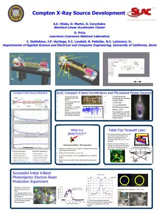
1.40 1.45 1.50 1.55 MeV What is a photoinjector? SLAC Compact X-band Accelerators and Microwave Power Sources UV Laser light 6 ft e- Cu Photoelectric Effect + RF Acceleration • Emission of electrons from surface is characterized by laser pulse shape and intensity • Pulse can be very short. ( 0.1-1 ps) • Current can be high. ( 0.5 nC charge630 A for an 800 fs pulse) • Beam size can be small. Size is determined by laser pulse shape. • RF fields can be very high. ( 200 MeV/m) Solenoid and Photoinjector Waveguide from Klystron Waveguide Window Solenoid and Photoinjector Electron Beam Diagnostics Camera Laser Feedthru / Electron Beam Diagnostics Quadrupole Magnets Linac Linac Quadrupole Magnets Compton X-Ray Source Beamline Dipole Corrector Magnet Gate Valve Vacuum Pumpout • X-band permits high gradients of up to 75 MV/m • Four times smaller than conventional technology • Focusing of ~ kA beam to 30 microns in < 2 meters • Opens up a new energy and intensity frontier to the medical community X-band 1.05 m long accelerator structure • X-band klystrons developed for the Next Linear Collider • 11.424 GHz • 1.5 ms pulsewidth • 60 MW output power • 420 kV, 327 A • Two klystrons used for CXS-10; however, the clinical device will use a single source Processing accelerator structure to 75 MV/m • Interaction parameters: • Energy spread Dg/g < 1% • Energy tunable 25 – 60 MeV • Peak current 630 Amperes • Emittance 1 p mm-mrad • Focal spot 20 micron diameter • Cathode parameters: • Ultraviolet laser 266 nm • Flat-top duration 800 fs • Electron bunch charge 500 pC • Quantum efficiency 2 x 10⁻⁵ • Uniform emission radius 0.25 mm Energy (MeV) Cathode Quantum Efficiency = 2 x 10⁻⁵ 1.47 MeV sub-picosecond electron bunch produced with an energy spread of 1.8% at a gradient of over 100 MeV/m Compton X-Ray Source Development A.E. Vlieks, D. Martin, G. Caryotakis Stanford Linear Accelerator Center D. Price Lawrence Livermore National Laboratory C. DeStefano, J.P. Heritage, E.C. Landahl, B. Pelletier, N.C. Luhmann, Jr. Departments of Applied Science and Electrical and Computer Engineering, University of California, Davis Before aperture Table-Top Terawatt Laser • The same high field conditions that exist inside a synchrotron x-ray source are generated at the interaction point for only 5 x 10-14 seconds • Ultrashort optics techniques are utilized to synchronize and shape the laser for optimum electron beam and x-ray production TW pulse compressor 12 fs laser oscillator Successful Initial X-Band Photoinjector Electron Beam Production Experiment After aperture Before aperture Operation of the First X-band Photoinjector (8.6 GHz) First Implementation of an Ultrashort Pulse Laser into a Photoinjector Production of Low Emittance and Low Energy Spread Electron Beams Normalized rms emittance = 1.63 p mm-mrad Solenoids Phosphor Screen Trigger Photodiode Laser Energy Meter Faraday Cup
Pre-bonding 6 5 4 Bz (kG) 3 3D HFSS modeling to adjust Qext and frequency 2 1 Final Bonded Photoinjector Cavity 12 0 2 4 6 8 10 14 16 18 20 Z (cm) Post-bonding Bead-pull apparatus for cold testing of field profiles Field flatness maintained and frequency change quantified Input waveguide Ceramic Window Individual Tuning of Final Cells Frequency Sensitivity: Power Splitter Coax. antenna Cathode Beam Exit Water-cooling Endcaps Cells 2-5 Pump-out port Cell 6 Cell 1 The X-Band Photoinjector: A New Source of High Brightness Electron Beams Electromagnetic Simulations RF Gun 2D Electric Field Profile from SUPERFISH Cold test photoinjector cavity Cold Tests Emittance Compensation Solenoid Magnet Final Mechanical Design and Fabrication Waveguide Assembly Components • RF Design. • Beam dynamics design. • Manufacture of cold-test parts. • Diffusion bonding of cold-test Injector. • Re-measurement of cold-test Injector. • Coupler redesign. • Manufacture of final Gun parts • Cold testing/tuning of final gun parts. • Assembly/diffusion bonding • High Power tests underway Structure Bonding Waveguide Assembly Photoinjector cells in bonding furnace