DHCP Configuration and Relay Agent Setup in Ethernet and PSTN Environments
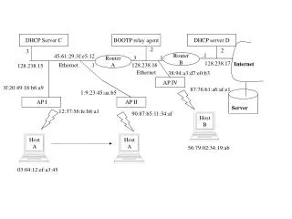
This document outlines the DHCP server configuration, including the setup of a BOOTP relay agent and various network components such as routers and access points (APs). It describes the interactions between devices in a network, mapping out IP addresses and MAC addresses pertinent to DHCP operation. Additionally, it details the signaling and connections within a PSTN (Public Switched Telephone Network) environment, including switches and their link weights for optimized routing. Relevant host interactions and HLR (Home Location Register) configurations are also discussed.

DHCP Configuration and Relay Agent Setup in Ethernet and PSTN Environments
E N D
Presentation Transcript
DHCP Server C BOOTP relay agent DHCP server D .2 .2 .3 .1 45:61:29:3f:e5:12 Router B .3 .1 Router A 128.238.17 Internet Ethernet .1 128.238.16 128.238.15 Ethernet 38:94:a3:d7:e0:b3 AP IV 3f:20:49:18:b6:a9 87:76:b1:a6:af:e1 1:9:23:45:aa:b5 AP I AP II Server 12:37:56:fe:b8:a1 90:87:b5:11:34:af Host A Host A Host B 56:79:02:34:19:ab 03:04:12:ef:a3:45
HLR for all 718-555 numbers SS7 Network HLR1 PSTN Switch C VLR2 PSTN Switch D 1 VLR1 1 1 GMSC/MSC2 3 GMSC/MSC1 1 415-555 PSTN Switch A 2 718-555 2 PSTN Switch E 3 1 PSTN Switch B 1 Link weights (used for shortest-path routing) 718-555-1234 212-555-5672 Signaling link Trunk