Download
1 / 13
130 likes | 283 Views
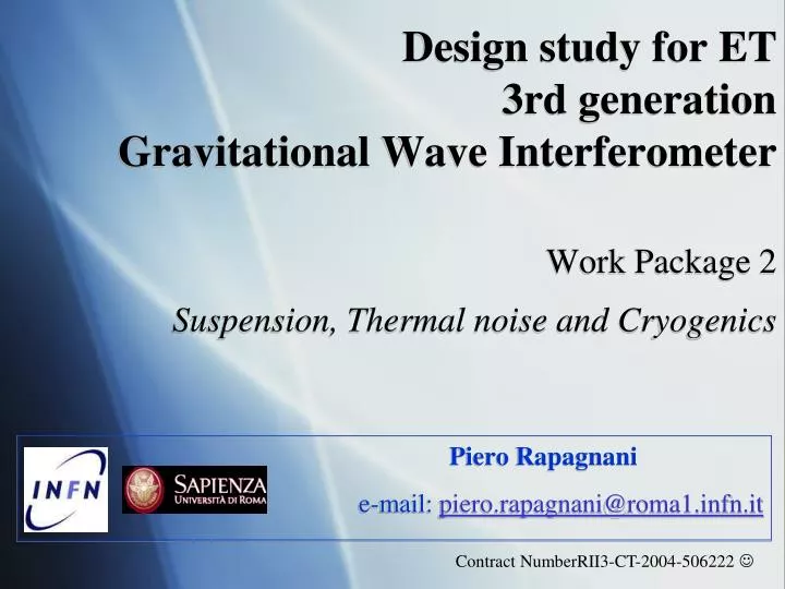
Design study for ET 3rd generation Gravitational Wave Interferometer Work Package 2 Suspension, Thermal noise and Cryogenics. Piero Rapagnani e-mail: piero.rapagnani@roma1.infn.it. Contract NumberRII3-CT-2004-506222 . The Challenge:

E N D
Design study for ET3rd generation Gravitational Wave InterferometerWork Package 2Suspension, Thermal noise and Cryogenics Piero Rapagnani e-mail: piero.rapagnani@roma1.infn.it Contract NumberRII3-CT-2004-506222
The Challenge: • Find a way to push the sensitivity of a gw detector as near as possible to 1 Hz • Underground • Passive and active seismic attenuation • Low dissipation materials for mirror suspensions • Cryogenics
Partecipants: • 1 - EGO (FRA-ITA) • 2 - INFN (ITA) (GE, FI, NA,PI, PG, RM1, RM2) • 3 - MPG (DEU) • 4 - CNRS (FRA) • 5 - University of Birmingham (UK) • 6 - University of Glasgow (UK) • 7 - VU (NL) • 8 - University of Cardiff (UK) + Science Team
Month 1-33 Month 1-12 Month 1-15 Month 10-26 Month 12-26 Month 10-24 Month 10-26 Month 26-33 Thermal Noise Requirements for the Suspensions of the 3rd Gen ITF - Task ID 18 Material Intrinsic losses requirements at low temperatures Seismic Attenuation Requirements of the suspension (100 days – M15) Suspension seismic attenuation requirements (input from site selection) Identification of control strategy and optimal mode frequencies for suspension elements Preliminary Conceptual Design of the overall Cryogenic Suspension (360 days – M24) Upper Suspension preliminary Design: Active vs. Passive Super Attenuator (4 Months) Conceptual design of damping, alignment and control strategy (12 Months) Cryogenic compatibility of Upper Suspension Design (12 Months) Last Stage Suspension Preliminary Design (300 days - M24) Test Mass Requirements (3 Months – M13) Test Mass Definition (4 Months – M23) Suspension Wires material and size choice (Input from Material Selection) Definition of last stage actuation strategy and technology Cooling Requirements and Cooling Strategy definition (360 days - M26) Thermal Path definition and Thermal Links Requirements (6 Months - M21) Thermal Links Conceptual design (6 Months – M26) Finalization of the Conceptual Design of the Overall Cryogenic Suspension P. Rapagnani
Material Intrinsic losses requirements at low temperatures (12 Months – M12) Identify the materials with best properties for: Mirror Bulk, Mirror Coating, Mirror Suspension Wires Quantify the constraints from the thermal, optical and anelastic point of view and identify possible tradeoffs. Identify a possible R&D path to materials selection. Seismic Attenuation Requirements of the suspension (100 days – M26) Suspension seismic attenuation requirements (3 Months – M26) (input from site selection) Identification of control strategy and optimal mode frequencies for suspension elements An extended simulation of the suspension must be developed, where the best control strategy can be identified and tested. It is necessary to verify that the system has no mechanical modes which involve critical degrees of freedom and are not sensitive to the foreseen control loops. P. Rapagnani
Preliminary Conceptual Design of the overall Cryogenic Suspension (12 Months – M23): Upper Suspension preliminary Design: Active vs. Passive Super Attenuator (4 Months) Conceptual design of damping, alignment and control strategy (12 Months) Cryogenic compatibility of Upper Suspension Design (12 Months) Identify the constraints on the upper suspension elements due to the connection with the low temperature last stage elements. Identify a suspension interface between last stage element and suspension chain which minimize thermal conduction. Last Stage Suspension Preliminary Design Test Mass Requirements (460 days – M22) Test Mass Geometry and Size definition (Input from Optical Configuration) Test Mass Mechanical and Optical losses requirements (12 Months – M12) Test Mass Definition (4 Months – M23) Suspension Wires material and size choice(Input from Material Selection) Definition of last stage actuation strategy and technology Actuation and Sensing at low temperatures allow the use of superconducting techniques which are the lowest noise technologies available, at the cost of an increased complexity of the system and of the necessity to be at low temperatures to make it work. It is possible to design hybrid systems which could have traditional sensing and actuation, working also at room temperature, in parallel with superconducting low noise sensors, which could be used once the proper operating point of the antenna is reached. P. Rapagnani
Cooling Requirements and Cooling Strategy definition Identify the requirements on test mass temperature in order to have a negligible thermal noise, with respect to seismic, newtonian and radiation pressure noises. Identify the best cooling strategy (refrigeration only, cryogenic liquids, hybrid techniques) regarding: underground facilities safety and costs (input from site selection), power to extract from the test mass (input from mirror optical properties) noise input constraints Thermal Path definition and Thermal Links Requirements Identify the best possible path depending on the cooling strategy: tradeoff between the necessity to have a short thermal link and a very low frequency, (hence very long) connection of the mirror to the refrigeration apparatus. Identify the constraints on the acoustic attenuation chain for the thermal links. Thermal Links Conceptual design (3 Months – M24) Finalization of the conceptual design of thermal links attenuation chain, i including the thermal contacts between refrigeration apparatus and last stage elements. P. Rapagnani
Following the approval of the ET Design Study: • Definition of tasks and tasks responsibles together with involved groups • Kick-off meeting of the WP2 activity • Periodic (bimonthly?quarterly?) meetings • Encourage exchanges and coordination between The involved groups and with other groups in the Science Team P. Rapagnani
The Prototype of Cryogenic Payload Mirror suspended by silicon strips attached with silica bonding (Present suspensions are copper strips) We have designed and built a cryogenic payload scaled 1:3.5 compared to the VIRGO standard Marionette hosting the central insert made of silicon (at present the central insert is made of Al) Electromagnetic actuators like the Virgo mirrors lateral ones (macor support, copper wire kapton insulated) Reaction mass of the mirror made of copper, gold coated Silicon mirror (Preliminary assembly with a fake aluminum mirror) P. Rapagnani
Minipayload Mechanical Modes(room temperature measurements;Noise injected by coils)sensor monitoring the mirror position 10 10-1 10-3 10-5 10-7 10-9 Frequency [Hz] V/(Hz)1/2 Torsional mode Pendulum mode October, 27 2006 10 P. Rapagnani Paola Puppo ILIAS Meeting - London
Cooling test on the small scale payload prototype Fiber Bundle Sensor October, 27 2006 11 P. Rapagnani
Next steps Improve the vibration reduction scheme To modify the sensing scheme to improve the noise floor at closed loop to the control of the horizontal degrees of freedom ; Full scale cryogenic payload (with silicon) Test a full scale silicon mirror at cryogenic temperature in the EGO cryostat in Cascina, Virgo Site; To define in a realistic way the refrigeration procedure The properties of the full scale silicon mirror. 12 P. Rapagnani
Cryo-Compatible Superattenuator design Pintracavity= 500 kW acoating=1ppm Pcoating=500 mW • High Thermal impedance • MRM wire • The upper part is thermally • insulated by thermal screens 13 P. Rapagnani