Download

1 / 19
190 likes | 238 Views
This article explores the different baffle designs in shell and tube heat exchangers for improved fluid flow and heat transfer efficiency. It discusses the types of baffle plates, their impact on heat transfer coefficients, and the thermal analysis process involved in rating, designing, and selecting heat exchangers. Learn about basic design procedures and selection criteria for optimal heat exchanger performance.

E N D
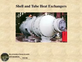
The Family of Shell and Tube Heat Exchangers P M V Subbarao Professor Mechanical Engineering Department I I T Delhi Family members with Simple Geometrical Features for Complex Fluid Flow….
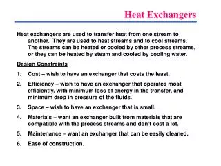
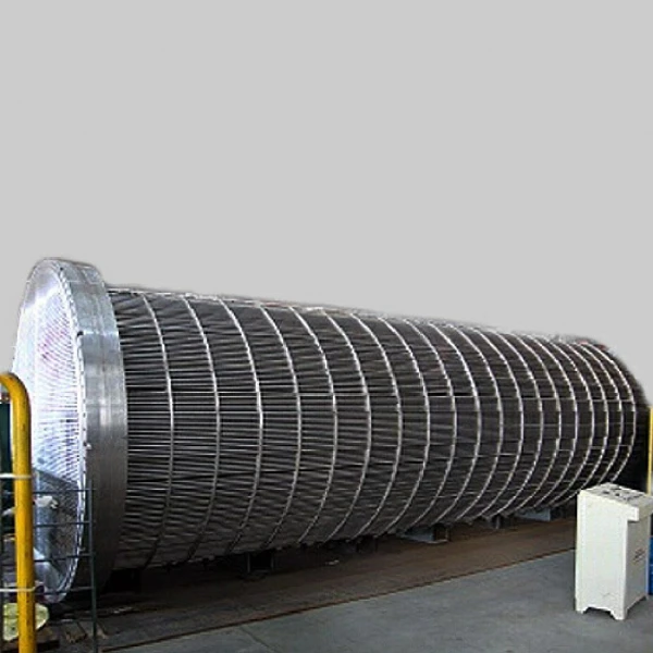
Cross Baffles • Baffles serve two purposes: • Divert (direct) the flow across the bundle to Wet the the maximum tube surface area. • Support the tubes for structural rigidity, preventing tube vibration and sagging. • When the tube bundle employs baffles, • The heat transfer coefficient is higher than the coefficient for undisturbed flow around tubes without baffles. • For a baffled heat exchanger the higher heat transfer coefficients result from the increased turbulence. • the velocity of fluid fluctuates because of the constricted area between adjacent tubes across the bundle. • This also leads to developing flow for ever.
Types of Baffle Plates : Segmental Cut Baffles • The single and double segmental baffles are most frequently used. • They divert the flow most effectively across the tubes. • The baffle spacing must be chosen with care. • Optimal baffle spacing is somewhere between 40% - 60% of the shell diameter. • Baffle cut of 25%-35% is usually recommended.
Double Segmental Baffles Triple Segmental Baffles Types of Baffle Plates The triple segmental baffles are used for low pressure applications.
Types of Baffle Plates Disc and ring baffles are composed of alternating outer rings and inner discs, which direct the flow radially across the tube field. § The potential bundle-to-shell bypass stream is eliminated § This baffle type is very effective in pressure drop to heat transfer conversion
Types of Baffle Plates In an orifice baffle shell-side-fluid flows through the clearance between tube outside diameter and baffle-hole diameter.
Thermal Analysis of Heat Exchanger • Known as heat exchanger specification problems and their solutions. • These are ‘rating’, ‘design’, and ‘selection’.
Rating Analysis • The rating problem is evaluating the thermo-hydraulic performance of a fully specified exchanger. • The rating program determines: • the heat transfer rate and the fluid outlet temperatures for prescribed fluid flow rates, inlet temperatures, and • the pressure drop for an existing heat exchanger; • therefore the heat transfer surface area and the flow passage dimensions are available.
The Design (Sizing) Analysis • ‘Design’ is the process of determining all essential constructional dimensions of an exchanger that must perform a given heat duty and respect limitations on shell-side and tube-side pressure drop. • In the Design (sizing) Analysis, • An appropriate heat exchanger type is selected. • The size to meet the specified hot and cold fluid inlet and outlet temperatures, flow rates, and pressure drop requirements, is determined. • Constraints: • Minimum or maximum flow velocities, • Size and/or weight limitations, • Ease of cleaning and maintenance, erosion, tube vibration, and thermal expansion. • Each design problem has a number of potential solutions, but only one will have the best combination of characteristics and cost.
Basic Design Procedure • Heat exchanger must satisfy the Heat transfer requirements (design or process needs) • Allowable pressure drop (pumping capacity and cost) • Steps in designing a heat exchanger can be listed as: • Identify the problem • Select an heat exchanger type • Calculate/Select initial design • parameters • Rate the initial design • Calculate thermal performance and pressure drops for shell and tube side. • Evaluate the design. • Is performance and cost acceptable?
The Selection Analysis • ‘Selection’ means choosing a heat exchanger from among a number of units already existing. • Typically, these are standard units listed in catalogs of various manufacturers. • Sufficient manufacturer’s data usually exist to allow one to select comfortably oversized exchanger with respect to both area and pressure drop.