Download

1 / 27
280 likes | 372 Views
Learn about the primary parameters in machining operations and how to calculate the necessary power requirements. Explore various machining processes, their advantages, and challenges. Discover the essential turning, drilling, and milling operations along with their parameters.

E N D
Name the three primary parameters that must be specified for a machining operation. • These three parameters allow us to decide if we have the power to physically perform the operation. What (three letters) calculation can we get from the primary parameters to begin to address the necessary power requirements? Bonus Quiz 1
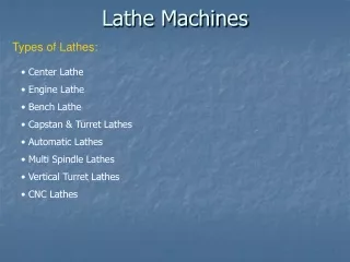
Four classes of Processing Operations: • Solidification Processes • Particulate Processes • Deformation Processes • Material Removal Processes • Two classes of Assembly Operations: • Mechanical Assembly • Joining Manufacturing Operations
Variety of work materials can be machined • Most frequently applied to metals • Variety of part shapes and special geometry features possible, such as: • Screw threads • Accurate round holes • Very straight edges and flat surfaces • Good dimensional accuracy and surface finish • Wasteful of material • Chips generated in machining are wasted material, at least in the unit operation • Time consuming • A machining operation generally takes more time to shape a given part than alternative shaping processes, such as casting, powder metallurgy, or forming Machining
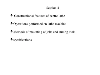
Generally performed after other manufacturing processes (casting, forging, …) • Other processes create the general shape of the workpart • Machining provides the final shape, dimensions, finish, and special geometric details that other processes cannot create • Most important machining operations: • Turning • Drilling • Milling • Other machining operations: • Shaping and planing • Broaching • Sawing Machining Operations
Cutting Speed – (v) • Primary motion • Peripheral speed m/s ft/min • Feed – (f) • Secondary motion • Turning: mm/rev in/rev • Milling: mm/tooth in/tooth • Depth of Cut – (d) • Penetration of tool below original work surface • Single parameter mm in • Resulting in Material Removal Rate –(MRR) MRR = v f dmm3/s in3/min where v = cutting speed; f = feed; d = depth of cut Primary Machining Parameters
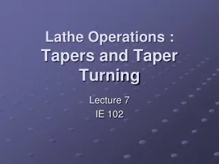
Figure 22.5 ‑ Turning operation [Groover (2004), p.503] Turning Parameters Illustrated
Creates a round hole in a workpart Contrasts with boring which can only enlarge an existing hole Cutting tool called a drill or drill bit Customarily performed on a drill press Drilling Figure 21.3 (b) drilling [Groover (2004), p.501]
Milling Parameters Illustrated Figure 21.3 ‑ Two forms of milling: (a) peripheral milling, and (b) face milling [Groover (2004), p.516] IENG 475: Computer-Controlled Manufacturing Systems
Machining Operations & Parameters IENG 475: Computer-Controlled Manufacturing Systems
Cut Types: Roughing & Finishing IENG 475: Computer-Controlled Manufacturing Systems
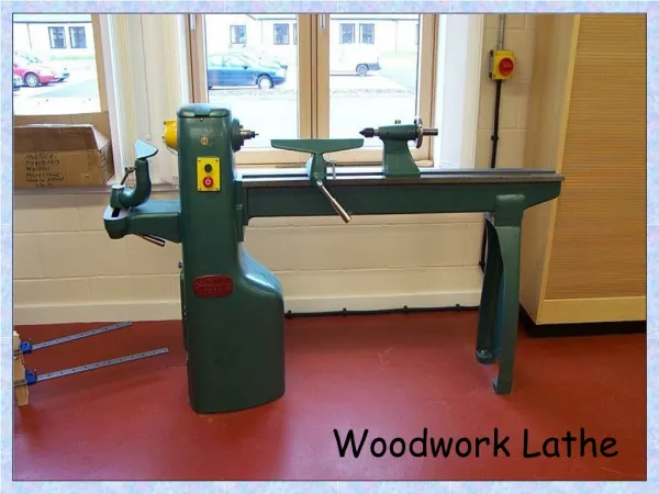
A single point cutting tool removes material from a rotating workpiece to generate a rotationally symmetric shape • Machine tool is called a lathe • Types of cuts: • Facing • Contour turning • Chamfering • Parting (Cut-off) / Grooving • Threading Turning IENG 475: Computer-Controlled Manufacturing Systems
Figure 22.5 ‑ Turning operation [Groover (2004), p.503] Turning Parameters Illustrated IENG 475: Computer-Controlled Manufacturing Systems
Figure 22.6 (a) facing Tool is fed radially inward Facing
Instead of feeding the tool parallel to the axis of rotation, tool follows a contour that is not necessarily straight (thus creating a contoured form). Contour Turning Figure 22.6 (c) contour turning
Right Hand Tool: • Cuts from right to left • Left Hand Tool: • Cuts from left to right Right & Left Hand Tools
Cutting edge cuts an angle on the corner of the cylinder, forming a "chamfer" Chamfering Figure 22.6 (e) chamfering
Tool is fed radially into rotating work at some location to cut off end of part, or provide a groove Parting (Cutoff) / Grooving Figure 22.6 (f) cutoff
Pointed form tool is fed linearly across surface of rotating workpart parallel to axis of rotation at a large feed rate, thus creating threads Threading Figure 22.6 (g) threading
Figure 22.7 Diagram of an engine lathe, showing its principal components Engine Lathe
Manual operation is replaced by a “turret” that holds multiple tools • Tools are rapidly brought into action by indexing the turret • Tool post is replaced by multi‑sided turret to index multiple tools • Applications: high production work that requires a sequence of cuts on the part Turret Lathe
Spindle Speed Tool Turret + X-axis Ways + Z-axis Cross Slide Spindle CNC Turret Lathe
Right Hand Profile Tool Chuck CNC Lathe: Air-Operated Chuck
Left Hand Profile Tool Tool Turret Grooving / Parting Tool Tool Holder CNC Lathe: Tool Turret Right Hand Profile Tool
Spindle Speed - N (rpm) • v = cutting speed • Do = outer diameter • Feed Rate -fr(mm/min -or- in/min) • f = feed per rev • Depth of Cut - d (mm/rev -or- in/rev) • Do = outer diameter • Df = final diameter • Machining Time - Tm(min) • L = length of cut • Mat’l Removal Rate - MRR (mm3/min -or- in3/min) Machining Calculations: Turning
Finish Machining (Drilling & Milling) Next Week: • Next Topic: Process Planning • Following Week: Group Technology • Lab this week: • Fixturing (manual tools & drill press) • Lab next week: • Manual Lathe & Mill Operations: • Rough & Finish Profiling Cuts • Facing Cuts • Parting Cuts • Tool Changes • Touch-Off Questions & Issues