Download
1 / 9
90 likes | 178 Views
Alcuni moduli per processare i segnali provenienti dai rivelatori. Ortec 579 Fast Filter Amplifier Ortec 571 Amplifier Ortec 142AH Preamplifier (http://www.ortec-online.com/products.htm). Ortec 579. Per fast timing di rivelatori a semiconduttore Tempo di salita < 8 ns

E N D
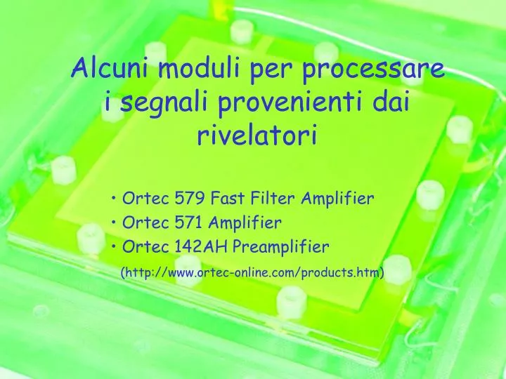
Alcuni moduli per processare i segnali provenienti dai rivelatori Ortec 579 Fast Filter Amplifier Ortec 571 Amplifier Ortec 142AH Preamplifier (http://www.ortec-online.com/products.htm)
Ortec 579 • Per fast timing di rivelatori a semiconduttore • Tempo di salita < 8 ns • Integrazione e differenziazione regolabili indipendentemente • Gated Baseline restorer • Pole-zero Cancellation • Capace di pilotare +-5V su 50 Ohm A. Cardini / INFN Cagliari
Ortec 579: diagramma a blocchi A. Cardini / INFN Cagliari
Ortec 571 • Simile a quello in figura (ma modello piu’ vecchio) • Amplificatore general-purpose • Uscita uni/bi-polare • Basso rumore • Ampio intervallo di guadagni • Controllo del tempo di shaping • P/Z cancellation • Auto/manual BLR A. Cardini / INFN Cagliari
Amplificatori: i controlli • COARSE GAIN Front-panel 6-position switch to select X15, X25, X50, X125, X250, and X500 gain factor. When internal X5 attenuator is used, the coarse gain factors represent X3, X5, X10, X25, X50, and X100, respectively. A continuously variable voltage gain of X0.9 to X500 can be obtained. (Gain reduced by factor of two when cable clip is used.) • FINE GAIN Front-panel single-turn potentiometer, continuously adjustable from 0.3 to 1.0. • P/Z Front-panel screwdriver adjustable potentiometer to adjust pole-zero cancellation for decay time constants from 25 µs to infinity. • DIFF Front-panel 7-position switch selects a differentiation time constant to control the decay time of the pulse. Decay time @2.2 tD with ti = Out. The tD settings include Out, 10, 20, 50, 100, 200, and 500 ns. • INT Front-panel 7-position switch selects an integration time constant to control the rise time of the output pulse. The rise time is @2.2 ti with tD = Out. The ti settings include Out, 10, 20, 50, 100, 200, and 500 ns. Rise time in the Out position is <5 ns, equivalent to a ti <2.3 ns. • INV/NONINV Front-panel locking toggle switch selects inversion or noninversion of the input signal. • BLR ADJ Front-panel screwdriver adjustment to set the Gated BLR threshold from ±50 mV to ±500 mV referred to the output. • BLR GATED/UNGATED Printed wiring board (PWB) jumper selects gated or ungated BLR operation. Factory-set in gated position. • BLR LED This feature enables the user to quickly adjust the BLR threshold setting near the noise peak. Front-panel LED indicates an output amplitude has exceeded the BLR threshold. The BLR LED can be used as a visual indicator of the output counting rate. A. Cardini / INFN Cagliari
Ortec 142AH • Charge sensitive preamplifier • Extremely Low Noise • Uscita: <5ns rise time, 500 s decay time • Fast output available (rise time < 5ns) • Ingresso di test per test e calibrazione della catena A. Cardini / INFN Cagliari
Ortec 142AH: schema a blocchi A. Cardini / INFN Cagliari
COMPLICATO! A. Cardini / INFN Cagliari
Uso di una catena completa • Preamplificatore 142AH collegato al rivelatore (o ad un iniettore di carica) • Shaper realizzato con 570 o 579 • Osservare segnali in uscita dallo shaper • Attenzione alle impedenze di ingresso e di uscita dei vari pezzi. Sono “strane”!!! • Variare a piacere i tempi di integrazione/differenziazione e/o shaping • Osservare cosa succede muovendo la regolazione del P/Z cancellation A. Cardini / INFN Cagliari