Download

1 / 27
270 likes | 448 Views
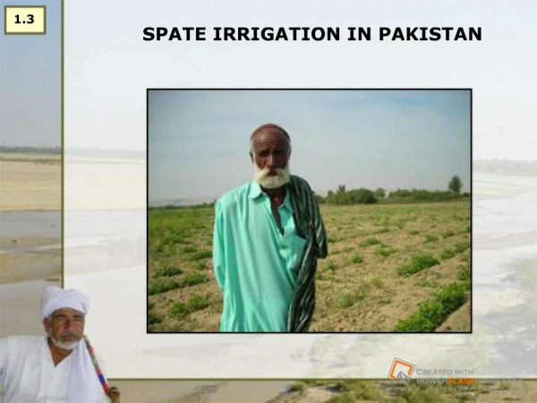
6.12a DESIGN APPROACH ON BILILO SPATE IRRIGATION PROJECT. Presented by Eyob Yehayis. 1. Project Area Description. Bililo spate is located at 42.75 N and 9.233E The average altitude is 1450 m. The annual mean rain fall is 757.15 mm. The annual effective RF=579.4mm

E N D
6.12aDESIGN APPROACH ON BILILO SPATE IRRIGATION PROJECT Presented by Eyob Yehayis
1. Project Area Description Bililo spate is located at 42.75 N and 9.233E • The average altitude is 1450 m. • The annual mean rain fall is 757.15 mm. • The annual effective RF=579.4mm • T max=31.6 and T min=15.6 oc • The Annual mean ETo=1902.77mm
1. Project Area Description Continued… • The cropping season starts in 15th march dominantly they produce sorghum. • The crop water required during the cropping season 579.14 mm. • The total effective rainfall during the cropping season is 338 mm. • Irrigation required = CWR-ERF = 259.69 mm
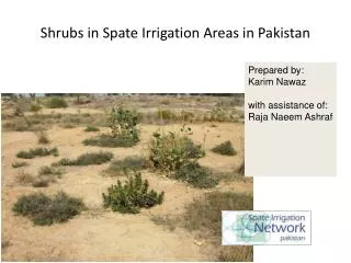
1. Project Area Description Continued… • The watershed Area is 157 km2 of which above 70% of it is covered by forest and scattered bushes, the rest is farmland. • About 25% of the cathment has a slope>28 % • The Project is almost it is a newly designed spate irrigation scheme.
2 The basic assumptions used for the project. • The system should be easy for farmers to operate and not require the large inputs of labor or other resources to maintain. • The system should prevent large and uncontrolled flood flows from damaging canals and field systems. • The system should Continue to function with high rates of sedimentation on the fields and canal beds.
3 Structural Component of The System 4.1 Weir (Diversion Head work) 4.2 Canal and Canal Structures
3.1 Weir (Diversion Head work) • The head work is modified to discharge the excess flood that is expected to come in 50 year return period. • Accordingly , the maximum flood for 50 years Return period is 110 3/s. • Designed to provides the required head to command the Farmland. • The intake canal sill level is 0.3 m above under sluice level.
3.2 Canal and Canal Structures 3.2.1 Flood Canal (Main canal) The design canal capacity is determined by the following assumptions: • The recession flood stays for 5 days • The farm land is provided with 25 cm flood water on one irrigation. • Farm land have chance of getting 2 flood water irrigation during the growing season. • The resulting design capacity is 3 m3/s for 500ha.
4.2. Flood Canal cont’ed… • The canal cross section and bed slope is designed on the maximum permissible velocity which satisfy 60% design flow to avoid the silt deposition on canal bed at lower flow. • Some of the canal cross section which passes porous and cliff formation is lined with masonry. • The secondary canal capacity is designed by proportioning the hectare it develops and multiplying by flood duration day ( 5 days).
4.2.1 Flood Canal cont’ed… Generally The System has: -Earthen canal on main canal 5 km on secondary canal 10.5km, 11 in number -Lined canal on main canal 2.3 km
4.2.2 Canal Structures • The system is provided with different farm structures which satisfies the hydraulic performance and structural stability depending on the land topography. • Accordingly, on the main canal there are: • 4 vertical drops • 32 inclined drops 7 of which on secondary canal • 1 flume • 5 division box • 4 chute 2 of which on SC1 • 3 Road crossing culverts
5 Water Management • It is assumed that only 1/5 of the command area is irrigated in one day starting from upstream toward the down stream. This could be changed based on the community interest.
6 Problem encountered • Estimating the frequency, amount and duration of the flood water in un gauged rivers. • Estimating the sediment yield with the respective runoff.