Download
1 / 31
410 likes | 1.14k Views
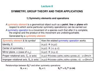
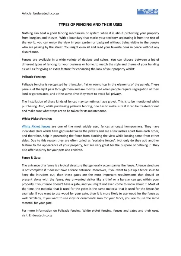
Instrumentation and Product Testing. Sixth Lecture Types of Transducers and Their Applications. 1.1 Distinction Between The Sensor And Transducer A sensible distinction is to use “sensor” for sensing element itself and “transducer” for the sensing element plus any associated circuitry.

E N D
Instrumentation and Product Testing Sixth Lecture Types of Transducers and Their Applications
1.1 Distinction Between The Sensor And Transducer A sensible distinction is to use “sensor” for sensing element itself and “transducer” for the sensing element plus any associated circuitry.
1.2 Active and passive transducers • Passive transducer • A component whose output energy is supplied entirely or almost entirely by its input signal is commonly called a passive transducer. • Active transducer • An active transducer requires an auxiliary source of power which supplies a major part of the output power while the input signal supplies only an insignificant portion. Normally, the output magnitude of the active transducer is higher than that of the passive type.
We can further classify transducers according to their • function (displacement, temperature, force) • physical property (inductive, photo-voltaic, piezo-electric)
2.1 Transducer of linear displacement Force and displacement are closely linked. A true/ideal displacement transducer is one which requires a negligible force to make a large displacement.
2.2 Analog Methods Resistive type The simplest linear displacement transducer is a linear potentiometer. Use a linear potentiometer as a linear displacement transducer
Features : • 1. Simple and cheap • 2. Accuracy depends on quality and dimension of the resistive wire used or the quality of the resistive film. • 3. The force required to operate, although small, depends on the size of the potentiometer, but that required to start movement of the slider is generally about twice that to keep it in motion. • 4. The frequency response is limited by the mass of the system but small transducer can have a flat response up to 50 or 60 Hz.
Main demerit : The output is very noisy when the slider moves. Cause of the noise are many: dirt and corrosion on the wire; chatting and vibration of the slider contact; variation of contact area as the slider moves; resolution noise when the slider makes and breaks contact with a turn of wire; etc.
Inductive type An important displacement transducer used in industrial and medical application is the linear variable differential transformer (LVDT).
F. Coil former; C. Movable core; P. Primary winding; S1 and S2. Secondary windings; E1. Induced voltage in S1; E2. Induced voltage in S2. Eo. Output voltage E1 - E2
(a) Absolute magnitude output voltage; (b) phase-referenced output voltage as a function of LVDT core position
Characteristics: 1. Due to no moving contact (non-contact) hence very low noise level. Resolution is excellent. 2. The frequency response is limited mechanically by the mass of the core and electrically by the frequency of the applied primary voltage (carrier), the frequency of this carrier should be at last ten times that of the highest frequency component to be measured. Demerits: 1. Quite expensive. 2. The operation can be severely affected by stray magnetic A.C. fields or by the presence of large mass of metal near by.
Capacitive methods The capacitance of a capacitor can be changed by varying its area, gap length or dielectric constant.
2.3 Digital methods By means of coding (absolute linear encoder) Identify the position of a movable test piece by a binary system of notation. • The resolution depends upon the number of bits comprising the binary number. • The accuracy obviously depends upon the accuracy with which the scale is drawn.
All the above mentioned methods are impractical when measuring long displacement (say > 1m) with good accuracy (say, <0.01mm). Such measurement may be required in many application areas, e.g. large machine tools. What should we do?
A grating measurement system can be though of as a development of a well-known mechanical-optical modulating transducer. Photo sensor output:
Gratings are available fairly cheaply in wide range of size. The resolution of measurement is essentially equal to the spacing between the lines. Gratings up to 1000 lines per mm are available.
3.1 Transducers of Angular displacement All the methods used in linear measurement can be applied to angular measurement. Analog Methods: Resistive, Inductive, and Capacitive Digital Methods: Absolute angular encoder, Use of maximal length, and Incremental angular encoder
4.1 Transducers of velocity By electronic differentiator or integrator As far as we know the linear displacement, finding of velocity can be done by differentiator. If it is an analog signal, op-amp differentiator may be used. If it is a digital signal, then use numerical methods for the differentiation. However, it is more usual to employ an acceleration transducer and an integrator, because differentiation accentuates the high frequency noise while integrating reduces the high frequency noise.
Induction method If a coil is moving inside a magnetic field is moved to cut directly across the lines of flux, then a voltage is induced in the coil : e = B a n v where B is the flux density a is area of the coil n is number of turn of the coil v is relative velocity between the coil and the field Therefore e is proportional to v, when other parameters are constant. There are mainly two types --- moving coil and moving magnet.
Doppler effect It is most common means of measuring remote moving objects. The police radar trap is a well known example of this technique. The Doppler effect is a very effective and accurate means of measuring velocity. If a narrow radio beam or ultrasonic beam is aimed at an object the beam will be reflected back to the source. However, if the object is moving the frequency of the received signal differs from that of the transmitted signal. The difference between the two frequencies being a measure of the velocity of the moving object. The received frequency will be higher than the transmitted frequency if the moving object is travelling towards the receiver and lower if the object is travelling away.
Digital methods By counting the number of pulse per unit time from the incremental encoder linear encoder, we can know the linear velocity. Its principle is the same as the digital method in angular velocity, hence please refer to that section for details.
4.2 Angular velocity • Analog method • Tachometer. There are two main types - • d.c. tacho and • a.c. tacho.
D.C. Tacho The device is very convenient and widely used in control systems where velocity feedback is required, but is unsatisfactory for precision measurement because of unavoidable ripple (due to the finite number of poles) and because of spikes due to the slip rings. The a.c. tacho is better in this respect.
A.C. Tacho The below shows two a.c. tachometer in which both the magnitude of the generated e.m.f. and its frequency are proportional to the angular velocity. A.C. tacho with moving magnet and stationary coils A.C. tacho with stationary magnet and coils Note: The direction of rotation is indicates by the sign of the DC voltage in DC tachometer, while AC tachometer does not indicate the direction of rotation.
Digital method By counting the number of pulses per unit time from a digital angular displacement encoder. The resolution depends on number of pulse per revolution of the encoder and the length of the unit time base.