Global Muon Trigger (Vienna)
300 likes | 502 Views
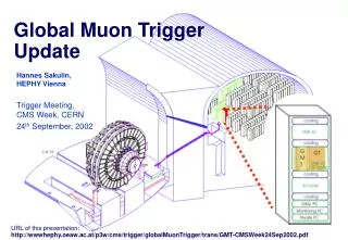
Global Muon Trigger (Vienna). Solution with 1 logic board. GMT Logic FPGA. old solution: cancel-out at DT and CSC track finder level confirmation by RPC in Global Muon Trigger maximum over-all efficiency is limited to the one of the RPC new solution:

Global Muon Trigger (Vienna)
E N D
Presentation Transcript
Global Muon Trigger (Vienna) Solution with 1 logic board
old solution: cancel-out at DT and CSC track finder level confirmation by RPC in Global Muon Trigger maximum over-all efficiency is limited to the one of the RPC new solution: duplication allowed at track finder level DT/CSC cancel-out unit in GMT ghosts are reduced independent of RPC more robust some (tolerable) ghosting remains Main Findings of CMS Internal Note 2002/024 GMT: DT/CSC cancel-out unit
Single muon trigger efficiency vs h |h| < 2.1 ORCA_6_2_2 (*)efficiency to find muon of any pT in flat pT sample
L1 single & di-muon trigger rates Trigger rates in kHz 100 kHz DAQ8 kHz for m, mm |h| < 2.1 50 kHz DAQ4 kHz for m, mm 20, 6;6eW =82.3 %eZ =99.6 %eBsmm = 9.9 % 12, 8;8eW =91.4 %eZ =99.7 %eBsmm =14.5 % 14, -;-eW =89.6 %eZ =99.8 %eBsmm =27.1 % 25, 5;5eW =74.1 %eZ =99.5 %eBsmm =14.3 % working points compatible with current L1 pT binning ORCA_6_2_2 L = 2x1033cm-2s-1 L = 1034cm-2s-1
GMT Status and Plans • Recent progress • Logic design completed • detailed design document & drawings • Functionality improved • added provision for Beam Halo Trigger during normal operation • Documentation • DT/CSC cancel-out unit improved performance in barrel/endcap overlap regionCMS Note 2002/024: H.Sakulin, “A Robust Solution to the Ghosting Problems of the CMS Level-1 Muon Trigger in the Barrel/Endcap Overlap Region” • Plans for 2002/2003 • continue VHDL simulation of FPGA chips • VHDL simulation of GMT board • Synthesis / design of FPGAs
GMT Milestones • Milestone Dec. 2001:Logic design done -> Done • Milestone Dec. 2002:FPGA design done -> Delayed to Dec. 2003 • Milestone Dec. 2003:VME board production done -> Delayed to June 2004 • Milestone June 2004:VME board tested (GMT ready) -> Delayed to Oct. 2004 • Milestone Jan. 2005:GMT integration tests done -> Planned on time
Global Trigger (Vienna) PSB (Pipeline Synchronizing Buffer) Input synchronization (7 boards including GMT) GTL (Global Trigger Logic) Logic calculation (1-2 boards) FDL (Final Decision Logic) L1A decision (1 board) TCS (Trigger Control System Modeule) Central Trigger Control (1 board) NEW: L1A (Level-1 Accept Module) Delivery of L1A (1 board) TIM (Timing Board) Timing (1 board) GTFE (Global Trigger Frontend) Readout (1 board)
Global Trigger Logic Prototype Board GTL-6U • GTL-6U Automatic chip design and setup procedure developed. Layout for a 20 channel GTL (4 , 4 isol. e/, 4 central jets, 4 fwd jets, SET, ETmiss, 8 jet multiplicities; other quadruplets can be connected alternatively for tests) has been finished! 1020-pin Altera FPGA 20k400E not yet included. The layout of a conversion board to be used later in final 9U-crate is ready. It contains also memories in FPGA’s to send simulated test data to the GTL-6U board. A decision on a redefinition of jet input groups has been taken. It was decided to keep the present best 4 central jets, 4 forward jets and 4 t-jets and jet multiplicities for different ET thresholds. A new quantity HT giving the transverse energy sum of all good jets above threshold has been added. The exact definition of how to calculate the jet multiplicities (h-range) still has to be taken at the level of the calorimeter trigger. More than 8 values could be necessary.
GTL-6U Prototype Schematics Design simplified, board available by June 2003
Final Decision Logic FDL-9U FPGA design has started. Board available by June 2003. • Monitoring of all algorithm and L1A bits • Prescaling of all algorithms • Trigger Mask • 8 L1A’s in parallel for partition modes • Input of up to 64 technical trigger bits from PSB possible
Timing Board TIM-6U • TIM-6U The board contains a TTCrx chip and provides all timing signals for the GT crate. It will also be used in the Drift Tube Track Finder crates. An FPGA provides all necessary test functions to run the crate without the central TTC clock. It simulates also L1A requests for monitoring or to test the readout chain. The schematic design is finished. The layout is in progress, decided to go ahead as planned with mezzanine TTCrx solution. The final Timing Board will be 6U (previously 9U) and is expected for June 2003.
Central Trigger Control System Board TCS-9U • TCS-9U • Its functions and the input / output cables are defined. Design of schematics and the TCS chip is in progress. The board is expected by April 2003. • Trigger Partitions: The maximum number of subsystems is fixed (32). An almost final agreement about the output to the DAQ Event Manager has been reached. The input format of Fast Signals is fixed. 4 coded bits per subsystem, sent as LVDS parallel data, and RJ45 connectors are proposed. The TCS board provides data for the ”TTCci” (new CMS-TTCvi). A L1A driver module to be used with the TTCci has been conceived.
TCS within Global Trigger New: 8 DAQ partitions (asynchronous TTS)
TCS board schematics VME L1A,BGo...to TTCci Clk,L1A,BC0...to 8 emulators TCS_fastsigs to 8DAQ_part TCS chip Clock PLL TCS monitoring chip
Preliminary GT event record for Event Manager Subdetector partitions are combined in groups connected to a DAQ partition. Only 1 DAQ partition triggers at a time due to DAQ restrictions. The same trigger type is valid for all members (=subdetector partitions) of this DAQ-partition.*) Begin of event BOR Identifier// Begin of record 32 bits Trigger number Nr of all L1Asent since begin of run (8h with 100kHz =ABA9 5000hex) 32 bits DAQ partition number 3 bits (30..28) , + Trigger Type 4bits (19..16), + Bunch crossing number 12 bits (11..0)32 bits Subdetector partitions // bit nn=1 Subd.-part. nn is connected to this DAQ-partition. 32 bits Event Number // since last ‚Reset Event Counter‘; 28 bits (27-0) **) 32 bits Orbit number // since last ‚Reset Orbit Counter‘; (29 bits=13.5h) **)32 bits Algo bits_0 Physics trigger algorithm bits 0...31 32 bits Algo bits_1 Physics trigger algorithm bits32...63 32 bits Algo bits_2 Physics trigger algorithm bits64...95 32 bits Algo bits_3 Physics trigger algorithm bits96...127 32 bits Algo bits_4 reserved for optional upgrade 32 bits Algo bits_5 reserved for optional upgrade 32 bits Technical trigger bits bits 31...0//also used for external test trigger signals 32 bits End of Event EOR Identifier// End of record 32 bits Preliminary Version 28 Aug 2002 Note: GPS time in EVM record also foreseen TCS FDL *) Therefore TCS does not send a (redundant) dedicated trigger type for each subdetector partition. **) Reset Event/Orbit Counter can be sent at different times to each single DAQ-partition. Data sources in Global Trigger crate: FDL = Final Decision board TCS = Central Trigger Control board
Global Trigger Setup Program Environment Task of GT Setup Program: Configure chips - via VME, JTAG (or from PROM) 2) Load registers, LUTs, memories - via VME Remarks: - For standard datataking, the trigger menu, setup of logic and thresholds from database (e.g. .xml) files, which are converted to HW format by custom or HAL device drivers. - For testing configuration files can also be loaded directly with Altera/Xilinx (e.g. MasterBlaster/ByteBlaster) hardware. - Run Control interfacing to be done. - JTAG programming not yet explored
Setup for GT Logic Configuration VME-MXI-2 Crate Controller VME-MXI-2 GTL-Conversion Card VME-Bus MXI Cable VME Crate Linux PC running XDAQ equipped with PCI-MXI Card Thanks to J. Gutleber for help with XDAQ!
Crate for Global Trigger Tests PSB-6U GTL Conversion Board VME MXI-2 Crate Controller
Global Trigger Milestones • Oct. 2002 (orig. March 2002):System Test -> Delayed to June 2003 • This includes the backplane-6U, the PSB-6U, GTL-6U, FDL-9U and TIM-6U. The GTFE and the GMT are not included. • Oct. 2002:Backplane-9U tested -> Delayed to March 2003 • Oct. 2002 (orig. July 2002):TCS-9U tested -> Delayed to April 2003 • June 2003:GTFE-9U tested -> Delayed to Dec. 2003 • Dec. 2003:20-channel Global Trigger tested -> Delayed to June 2004 • Milestone Dec. 2003:GMT ready -> Delayed to Jun. 2004 • July 2004:12-channel PSB-9U available • Nov. 2004:Complete 32-channel Global Trigger available • Includes GTL-9U module with all input channels(4 , 4 isol. e/, 4 non-isol. e/ , 12 jet channels, HT , SET, ETmiss, jet multiplicities).
Global Trigger Status Sept. 2002 • Custom Backplane for VME 9U crate • 6U Prototype: Channel Links ...existsMS 3/02* • 9U Backplane: 80MHz GTLp and Channel Links, ...design in progress MS 10/0203/03 • PSB Input board (synchronisation, monitoring) • 6 channel 6U Prototype: Channel Link receivers... board tested MS 3/02* • 12 channel board: memories inside FPGAs ...conceptual designMS 7/04 • GTL Logic board: • Conversion board for prototype ...board testedMS 3/02* • GTL6U prototype: 20 channels ...layout done MS 3/02* 06/03 • 4, 4ie/, 4 cjets, 4 fjets, ETT,mET, 8 nr_of jets • other quadruplets can be connected alternatively for tests • GTL9U board: 32 channels ...conceptual designMS 11/04 • 4, 4ie/, 4e/, 4 cjets, 4 fjets, 4 tau_jets,ETT,mET, HT, nrs_of jets • TIM Timing board...layout in progress MS 3/0206/03 • 6U size, TTCrx, clock and L1A distribution, also used by DTTF • FDL-9U Final Decision board...design in progress MS 3/0206/03 • TCS-9U Central Trigger Control board...design in progressMS 7/0204/03 • GTFE-9U Readout board...conceptual design MS 6/0312/03 • *) Milestone (MS) Mar-02: All prototype boards except GTFE+GMT.
Progress since 2001 • GTL-6U board: layout done • GTL Conversion board: produced and tested • Test program written in CVI with GUI • Configuration programimplemented using XDAQ. • TIM board: FPGA and board design done, layout in progress • TCS board: • Final definition of functions and IO-signals done, • Schematic and FPGA design in progress • FDL board: • Final definition of functions and IO-signals done, • Schematic and FPGA design in progress • Definition of requirements for the GT setup program in progress
Conclusions Global Muon Trigger Single board design for barrel and forward muons Solution for overlap region with DT/CSC cancel-out unit in GMT FPGA design started Global Trigger New processor crate layout, GTL layout finished, other boards well advanced, work on software requirements and solutions started Trigger Control System Interfaces to subsystems including Event Manager and partition handling defined This talk can be found at: http://wwwhephy.oeaw.ac.at/p3w/cms/trigger/globalTrigger/trans/ wulz_AnnRev_sep2002.ppt • Detailed information about the Global Trigger and the Global Muon Trigger is available on the HEPHY Vienna web sites: • http://wwwhephy.oeaw.ac.at/p3w/cms/trigger/globalTrigger • http://wwwhephy.oeaw.ac.at/p3w/cms/trigger/globalMuonTrigger