Download

1 / 26
310 likes | 1.02k Views
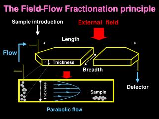
External Flow: Flow over Bluff Objects (Cylinders, Spheres, Packed Beds) and Impinging Jets. Chapter 7 Sections 7.4 through 7.8. Stagnation point: Location of zero velocity and maximum pressure. Followed by boundary layer development under a favorable pressure gradient

E N D
External Flow:Flow over Bluff Objects (Cylinders, Spheres, Packed Beds)andImpinging Jets Chapter 7 Sections 7.4 through 7.8
Stagnation point: Location of zero velocity and maximum pressure. • Followed by boundary layer development under a favorable pressure gradient and hence acceleration of the free stream flow . • As the fluid flows towards the rear of the cylinder, pressure increases. The boundary • layer develops under the influence of an adverse pressure gradient: Circular Cylinder in Cross Flow Cylinder in Cross Flow • Conditions depend on special features of boundary layer development, including • onset at a stagnation point and separation, as well as transition to turbulence.
Separation occurs when the velocity gradient becomes zero Cylinder in Cross Flow (cont.) followed by flow reversal and a wake downstream of the separation point.
Cylinder in Cross Flow (cont.) • Location of separation depends on boundary layer transition. • For Reynolds number > 200,000 on a smooth cylinder, the • boundary becomes turbulent. Flow separation is delayed, and • the wake is small then that when the boundary is laminar. • Drag force on the cylinder is the sum of friction and form (pressure) drag • Define drag coefficient: Where FD = Total drag force Af= Frontal area of cylinder = Diameter x Length
Cylinder in Cross Flow (cont.) Cylinder in Cross Flow: Experimental Drag Coefficient
Cylinder in Cross Flow (cont.) Cylinder in Cross Flow: Heat Convection Experiment
Cylinder in Cross Flow (cont.) Local Heat Convection Coefficient: Experimental Results
Experimental Data for Average Nusselt Number Turbulent Flow
Cylinder in Cross Flow (cont.) • Correlation of Average Nusselt Number: • Churchill and Bernstein • correlation for all ReD :
Flow characteristics similar to flow over cylinder. • Drag coefficient lower than that of cylinder because of 3D relief effect (Fig. 7.8) • Correlation of average Nusselt number (ms is the fluid viscosity at surface temperature): Forced Convection on Sphere Spheres and Packed Beds
Cylinder in Cross Flow (cont.) Cylinders of Noncircular Cross Section:
Flow Across Tube Banks Tube Banks • Typical design for two-fluid heat exchangers.
Tube Banks Definition of Max. Velocity Staggered: Aligned:
Aligned Tube Bank: Flow behind first row is turbulent, causing convection coefficients to increase gradually in subsequent rows if there are sufficiently spacings. If the rows are too close (ST/SL < 0.7), each tube is confined in the wake of the one in front, and convection coefficient would decrease instead. Tube Banks (cont.)
Staggered Tube Bank: Heat convection is more evenly distributed, and therefore more effective then the aligned tube bank. Tube Banks (cont.)
Tube Banks (cont.) • Zukauskas Correlation for an Isothermal Array:
Pr is evaluated at average of inlet and outlet temperature of the cross flow. Prs is evaluated at surface temperature of the tubes Ts. Reynolds number for the flow across the tube bank is defined as: ReD,max = Vmax D/n Tube Banks (cont.)
Tube Banks (cont.) • From an energy balance, it can be shown that the • inlet & outlet temperatures (Ti , To) of the flow is • related by: (Challenge: Prove it!) • N is the total number of tubes: • Total Heat Convection Rate can also be shown as: • As is the total surface area of the tubes: • DTlm is called the “Log-Mean Temperature”: • Correlation of Pressure Drop • across the tube bank:
Correlation Factor & Friction Factor: Aligned Tube Bank Tube Banks (cont.)
Correlation Factor & Friction Factor: Staggered Tube Bank Tube Banks (cont.)
Flow Through Packed Beds of Particles Spheres and Packed Beds • Large surface area per unit volume: desirable for the transfer and storage of thermal energy.
Spheres and Packed Beds (cont.) • Correlation For a packed bed of spheres: • jH is the Colburn j-factor: jH = St Pr2/3
Jet Impingement Jets • Characterized by large convection coefficients and used for cooling and heating • in numerous manufacturing, electronic and aeronautic applications.
Jets • Example of Multiple Jet Impingent Design: Slot Jet Array
Hydraulic diameter: Dh = 4 Area/Perimeter = D (round nozzle), Dh ~ 2W (slot nozzle) • Typical Experimental Data of Local Nusselt number distribution: Jets • Average Nusselt number: