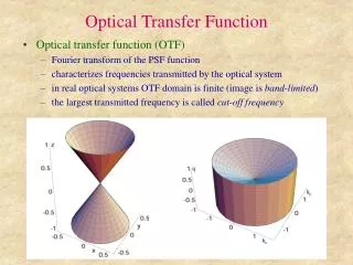
Understanding Modulation Transfer Function: Graphical Description for Image Quality Assessment
Learn about MTF, a method to assess system resolution quality, analyze object details transfer, evaluate noise elimination, and experimental MTF measurements in various imaging components. Discover how MTF helps in MTF measurement and system evaluation for image reconstruction and noise reduction. Explore MTF measurement techniques and the impact of modulation on image contrast.

Understanding Modulation Transfer Function: Graphical Description for Image Quality Assessment
E N D
Presentation Transcript
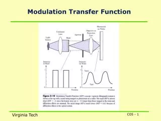
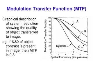
Modulation Transfer Function (MTF) Graphical description of system resolution showing the quality of object transferred to image. eg; If %80 of object contrast is present in image, then MTP is 0.8
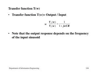
If object size (eg; The thickness of slit in a lead plate or Line in LSF) is , then spatial frequency is:Spatial Frequency =1/(2)
Frequency and space (time) are convertible to each other. Therefore, taking Fourier Transform of LSF we get MTF. h(x,y)=LSF
An object can be represented by its frequency components (Sinusoidal signals) using FT. • Then comparing these information with the MTF of system, we can evaluate the system to see if it can transfer the essential details (eg; Whether it can reconstruct the degraded information lost by Sampling) • FT of Noise is also useful to evaluate the system for transferring or eliminating noise information through the system. • FT of noise (Power spectrum or Wiener spectrum) is compared with the MTF of the system.
MTF measurement • A sinusoidal test phantom (a series of slits or square shape holes) is fixed in distance F from Source and d from Film. M=(F+d)/F Then, the image of slits at various size are obtained.
MTF measurement • Modulation (Contrast) of object is obtained for a point source as M’ • Where: • To = density changes • Tav = Average density on film • To+ = Maximum density • To- = Minimum density
MTF measurement • Modulation (Contrast) of image is obtained using the actual Focal Spot M • H(f) is less than 1, and It can be shown that H(f) is equivalent to FT of Focal Spot (PSF) with an addition of Magnification factor M. • Therefore for calculation of MTF, first FT of Focal Spot should be obtained, then its Frequency is modified (decreased) by M.
Experimental measurement of MTF • Input Modulation is: A = Amplitude • Output Modulation is: Usualy Output Modulation is smaller than Input Modulation Since the Modulation of both Input and Output are similar at frequency of 0, therefore MTF is 1 in zero frequency. In addition the MTF of Input is close to 1 at all frequencies. therefore, MTF of Output can be normalized and written as:
TungstenTarget Electrons (+) (--) Cu cathode Titling angle q Sin20° = 0.342, Sin16.5 =0.284 Apparent focal spot size X-Rays
17 MTF of various shape of Focal Spot
Focal Spots MTF depend on the shape and size of focal spot and magnification of image.For example; MTF of Square or Double pick focal spot is: M=Magnification m = M –1 a0 = focal spot width f = frequency of signal
Pinhole Source z Detector plane d
Finite source The total detected Intensity (image) of a transparent object (hole) having transmission t(x,y) = exp [ -µ (x,y) (z - zo)]imaged by a finite x-ray source, s(x,y) is obtained by convolution process: The detected image will be the convolution of a Magnified object and a magnified source. In frequency domain:
Square wave test patterna) in contact with Filmb) in contact with Screenc) same distance from filmMTF of Film MTF of Screen MTF of Target
Aliasing Oversampliny of LSF


![1. X resolution[95] AROC Curve BModulation Transfer Function CH D Curve DContrast-Detail Curve](https://cdn4.slideserve.com/1390808/slide1-dt.jpg)