Download
1 / 6
60 likes | 117 Views
PCB repair is a complicated process that requires appropriate test equipment and knowledge. Follow our quick guide to Repairing Circuit Boards, restoring damaged PCB

E N D
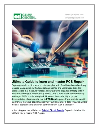
Ultimate Guide to learn and master PCB Repair Repairing small circuit boards is not a complex task. Small boards can be simply repaired via applying methodological approaches and using basic tools like oscilloscopes that measure voltages and waveforms at particular test points in the circuit and Digital multimeters (DMMs). On the other hand, troubleshooting multi-layer PCBs is a daunting task. However, the availability of proper documentation plays a crucial role in PCB Repair speed. If you are interested in electronics, there are good chances that you’ll encounter a dead PCB. So, what’s the best approach to follow when confronted with such a situation? In this blog post, we will discuss Printed Circuit Boards Repair in detail which will help you to master PCB Repair.
PCB repairis a complicated process these days. Manufacturing mistakes and frequent component failures have led to the increased numbers of PCB Repairs. Older Printed Circuit Boards can break down due to component failure, manufacturing errors, and incorrectly soldered parts, solder bridges and more. Though component changes and simple soldering require less complex fixes, some repairs require expert approaches to detect fault causes. Try to get a detailed report from the end user about how the PCB board failed? When was the last time it worked correctly? Try to find out what actually killed it! Does a software update have affected the PCB? Can you notice fault clues like broken wires or tracks? It’s wise to power up the damaged PCB first .For example, if there is a simple blow fuse, you should determine the reason for the issue instead of replacing the fuse. If PCB has been coated to protect it from moisture and dust that layer needs to be removed at least for a few important test points before you begin fault diagnosis. Conformal coating can be removed using solvents, or simply by peeling or blasting. Also, the coating can be pierced with the help of extremely sharp test pins. Before you begin PCB Repair, collect the relevant circuit diagrams and appropriate test equipment like solder/desolder hand tools, power supplies, DMM, an oscilloscope, etc. The most important tool to commence PCB Repair is the user report consisting of the details of how the failure occurred or what fault was observed. The most adaptable tool is the multimeter, but on the basis of PCB complexity, an LCR meter, power supply, oscilloscope, and logic analyzer may be required to examine the circuit’s operations. More sophisticated tools like spectrum analyzer can also be used to check signal levels and frequencies. Troubleshooting becomes much easier if a familiar good board is accessible so that visual and signal comparisons can be done. Lack of documentation and comparative board makes the challenge more frightening.
Complete Guide on Printed Circuit Boards Repair The most common repairs implemented on Printed Circuit Boards are the ones performed in the situations of heat and physical damage. Gather the necessary tools and equipment required for PCB Repairing: ●Sharp knife ●Flathead screwdriver ●Tweezers ●Soldering gun ●Scissors or craft knife
●Hot air gun ●Adhesive copper tape ●Pen ●Cotton swab and rubbing alcohol ●Paper clip Then follow our quick guide to Repairing Circuit Boards, restoring a damaged PCB to functionality. Step 1: Remove the damaged component. First, save the PCB to your work surface so that it doesn’t create any problem while you’re fixing it. You can use tape. Sometimes, detecting a damaged PCB demands the application of an oscilloscope to check the signal strengths. Also, sometimes it's required to look out the burned area indicating a failed component. If you are able to detect the non-functioning PCB components, there’s a simple process for replacing and removing it: ●Take the hot air gun and turn it on. Hold it no fewer than 6 inches from the faulty component. ●After some time, take a pair of tweezers and try to pick up the component away. If they don't come, extend to apply heat for a few more seconds and then try again. Use a sharp knife if in case the PCB pad has been damaged by heat. You should focus on limiting the amount of damage you do to Printed Circuit Boards and other nearby features while still leaving the board from any slags. Step 2: Clean the track and remove solder. After removing the damaged pad, continue removing the existing solder via a sharp knife. You may also use a sharp-pointed screwdriver or sandpaper instead of a sharp knife. No matter whatever you use, you should be able to get a fully exposed track which looks clean and shiny. Step 3: Place your copper tape over the track. After removing the damaged track and cleaning off the area, you should place your adhesive copper tape over the top of the area you’re working with. Your tape should be placed in such a way that it overlaps the existing track and covers the existing area through-hole.
Step 4: Solder the joints Now it is required to cautiously solder the joints where the new copper tape joins with the existing track on the restored PCB. Below are a few essential tips along with warnings about this part of the process: ●Copper tape melts swiftly at soldering temperatures. So you should always begin when you are certain that you can do this part of the process in one go. ●Use the minimum amount of heat and work studiously, but quickly, to minimize the amount of heat applied. Step 5: Restore the PCB through-hole Discover a hard implement with a rounded-off end, similar to a pen or another simple tool. Press down on the soldered area and rub firmly to make sure that the copper tape is properly affixed to the entire pad area. This technique will help you in identifying the through-hole, which can be later pierced with a paperclip or another similar implement. Step 6: Place and solder your component. After following the above-mentioned steps so far. Your PCB should have been restored to its original functionality and should be prepared to receive your component of choice. Now, soldering the components should not be a complex process to you. But you should keep the application of heat as minimum as possible. The new joint formed between the newly affixed copper tape and the track may be a little feeble. Step 7: Cut the excess tape from the repaired area. With the help of scissors or craft knife, trim the adhesive copper tape down to its size in order to finish the repair. It’s crucial to note that the recently repaired joint may restore your PCB to its right functionality, but the track, and joint will not be as structurally good as the original board.
There are dozens of hard and soft skills required to accomplish PCB repairs. There is actually not a fix order to follow for PCB Repairs. But you surely need excellent hand-eye coordination, detailed attention and patience. Continuous practice will help you to master this skill. Visit here: https://www.crimpcircuits.com/blog/ultimate- guide-to-learn-and-master-pcb-repair/