Download
1 / 25
250 likes | 267 Views
This article presents the results and conclusions of the hazard and accident analyses conducted for the ESS Target Station at the European Spallation Source. It provides an overview of the facility layout and target neutron science systems, and discusses the safety SSC identification and impact. The article also outlines the hazard analysis purpose and the bounding events identified for operations.

E N D
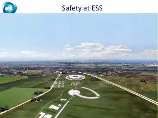
ESS Target Station Radiation Safety Accident Analyses Linda R. Coney European Spallation Source (ESS) ASW 2018 www.europeanspallationsource.se 22 August 2018
Outline • ESS Target Station Introduction • Hazard Analysis & Accident Analysis • Scope & Quantitative (AA) Procedure • Accident Analyses Results • Wheel & helium system • Safety SSC (structure, system, component) identification & impact • Conclusions
ESS facility layout Target Neutron Science Systems • 22 planned and budgeted neutron scattering instruments • Neutron beam line lengths ranging from 10 m to 150 m from source Proton Linear Accelerator • Long pulse proton beam 2,86 ms • Pulse frequency 14 Hz • Proton energy 2 GeV • Beam power, time averaged 5 MW, within pulse 125 MW • Beam current 62,5 mA
ESS Target Station Parameters • 5 MW long pulse spallation source • 2.86 ms proton bunch at 14 Hz rep rate • Raster pattern where protons incident upon Target wheel • Rotating tungsten target • 5.4 tons (4900 kg) wheel only, (11 tons wheel + shaft) • rotating at 23.3 rpm (sector receives beam pulse every 2.4 seconds) • 5 year lifetime, He gas cooled • Cold Moderators • Liquid hydrogen with 2-5 year lifetime • Inventories • High power beam impacting the tungsten target will create an inventory of nuclides • Primary inventory is in wheel (monolith and storage in active cells) • Keeping in Mind: • 450 – 500 employees, 2000 – 3000 users/year • facility is located in 100,000 inhabitant region
Key features of the ESS Target Station Moderator and reflector • Target Safety System • Monitors target coolant flow, pressure and temperature, monolith pressure, & target wheel rotation • Prohibit beam on target if parameters are outside specified limits • Helium cooling of target material • Mass flow 3 kg/s • Pressure 11 bar • Temperature inlet/outlet 40 °C/240 °C proton beam instrumentation plug monolith vessel • Rotating solid tungsten target • 36 sectors • Mass, total 11 tonnes, with 3 tonnes of W • Rotates 23.3 rpm, synchronized with pulsed proton beam 14 Hz neutron beam extraction port target monitoring plug protonbeam target wheel • Diagnostics and instrumentation • Controlled and integrated commissioning and operation of the accelerator and target • Fluorescent coating of PBW and target front face • Optical paths, grid profile monitor, aperture monitor • Wheel monitoring including position, temperature, vibration, as well as internal structure protonbeam window • Moderators • Provisional locations of moderators above and beneath the target wheel, i.e. monolith centre • 1st MR plug exploits the upper space, offering: • Cold, 30 mm high, liquid H2 moderators, 17 K • Thermal, 30 mm high, H2O moderator, 300 K
Outline • ESS Target Station Introduction • Hazard Analysis & Accident Analysis • Scope & Quantitative (AA) Procedure • Accident Analyses Results • Wheel & helium system • Safety SSC identification & impact • Conclusions
Hazard Analysis Purpose • Protect ESS workers and the public from accidents with potential radiological consequences • Hazard Analysis is a systematic process to identify, evaluate, and control potential hazards and accidents related to the Target Station. • Identify & understand hazardous scenarios associated with the facility operations, work activities, and natural phenomena • Define necessary mitigating measures g Input to design requirements • Accident Analyses – set of formalized design basis accidents identified from hazard analysis • 350 Top Events from qualitative HAs • Selected 22 bounding scenarios for further study • If prevented or mitigated, no additional safety functions required for group
Accident AnalysesBounding Events for Operations Monolith/Utility Block Events Active Cells Facility Events • Target wheel rotation stop during beam on • Beam Event: Focused & non-rastered beam • Loss of target wheel cooling during beam ON – includes AA4, AA7, AA8 PIEs • Leakage from target cooling circuit into monolith – beam OFF • Global bypass or local blockage of wheel cooling • Increased radiation level in target helium cooling system • Leakage between target He cooling system & intermediate water system – beam OFF • Loss of confinement in target He system – release into utility rooms – beam OFF • Moderator hydrogen combustion • Water leakage in monolith • Water leakage in connection cell and utility rooms • NBG/Chopper failure – projectile effect on monolith system (part of AA9) • High power beam on beam dump • Earthquake scenario – monolith • Fire in He purification getters • Active Cells: Worker inside maintenance cell when intrabay door opens • Active Cells: Worker exposed to worst case inventory in process cell • Active Cells: Worker exposed to worst case inventory in maintenance cell • Active Cells: Loss of HVAC (loss of dynamic confinement) • Active Cells: Loss of confinement – open doors/hatches • Active Cells: Fire • Active Cells: Earthquake scenario Target & He Cooling
Accident Analyses:Evaluate unmitigated events • Describe system • Identify baseline assumptions – safety functions present in normal operations • Quantitative determination of event category (H2,H3,H4,H5) all PIEs • Describe evolution of event • Include simulations, calculation of effect on local & neighboring systems • Calculate inventory • Determine amount of radioactive material released during accident • Source term = MAR(material at risk)* DR (damage ratio) * ARF(airborne release fraction) • Identify leak paths & points of emission for released material • Identify flow rates along leak path • Emission points – 10 m, 20 m, 30 m, 45 m • Calculate dose consequence to public reference person • Apply point of emission – use worst case weather conditions • Duration based on release & flow rates • Risk ranking for unmitigated event • Identify need for risk reduction measures to prevent or mitigate event
Outline • ESS Target Station Introduction • Hazard Analysis & Accident Analysis • Scope & Quantitative (AA) Procedure • Accident Analyses Results • Wheel & helium system • Safety SSC identification & impact • Conclusions
Accident Analyses: Focus on Loss of Cooling Accident (LOCA) Target & Helium Cooling Events • Target wheel rotation stop during beam on • Beam Event: Focused & non-rastered beam • Loss of target wheel cooling during beam ON – includes AA4, AA7, AA8 PIEs • Leakage from target cooling circuit into monolith – beam OFF • Global bypass or local blockage of wheel cooling • Increased radiation level in target helium cooling system • Leakage between target He cooling system & intermediate water system – beam OFF • Loss of confinement in target He system – release into utility rooms – beam OFF Evaluated in 2017 Releases: Helium coolant, Tungsten, Moderator water, Beryllium Conservative event development analysis Tungsten mass damaged: 1121 kg Oxidized W ARF: 0.005 g 5.6 kg released g Unmitigated dose: 75 mSv
TOAST Experiment Setup(Tungsten Oxidation AeroSol Transport) Flowcontrol Outlet Filter • How much tungsten becomes airborne by tungsten oxidation at high temperatures (> 1400 C)? • Measure Airborne Release Fraction, ARF= mass fraction of the oxidised amount that is airborne after passage through the system Windowcooling Air Inlet Insulation Pipe Impactor TC2 ~0.5 m/s Heating coil DMS2 AerosolMeasurements DMS1 – Differential Mobility Spectrometer 3 * 1 m, 1.5” TC1 – Thermocouple IR thermometer Flange Sample Sample Pressurised air Inductive Heating Stainless Sacrifice T IR Thermocouple
Oxides from TOAST Test 3 Remaining = 155 g(of 229 g) 74 g W removed Scales in vessel ~ 25 g W Deposits in pipe ~ 22 g W 34 g WO3 Captured in filter ~ 27 g W ARF = W mass in filter/W mass lost from block (27/74) W mass in filter calculated from the filter mass of oxide assuming it to be tungsten trioxide. ARF ~ 0.4
Unmitigated Monolith Events H2, H3 event Emission 30 m • Wheel • Stops rotating (AA1) • Beam as aggressor (AA2) • Loses cooling (AA3) • Leak in system • Fail HEX, int H20 system • Loss flow • Temperature increases, shroud melts, helium released g loss of monolith confinement • Moderator water released/evaporated • Part of spallation material spills into monolith, oxidizes & released • TOAST results required update to ARF and AA • Part of spallation material melts • Worst leak path – directly out of monolith via pressure relief system Public limit 0.1, 1.0 mSv gMitigation required • Unmitigated revised: • More realistic analysis due to TOAST • New amount released, new timing, new leak path rules g new doses
Significant Changes in AA3: 2017 g 2018 • Updated AA3 report undergoing document review & approval process
Outline • ESS Target Station Introduction • Hazard Analysis & Accident Analysis • Scope & Quantitative (AA) Procedure • Accident Analyses Results • Wheel & helium system, Monolith, ACF • Safety SSC identification & impact • Conclusions
Selection of Safety Functions:Monolith – Public Prevent release • TSS stops beam on low wheel speed, high temperature and low flow in He cooling (AA1, AA3) Limit event progression/limit release • TSS stops beam on high monolith pressure & low He cooling pressure (AA2, AA3) Control release • Monolith confinement (AA2, AA3) • Controlled relief path to height (AA3) • Determine required safety functions • Hierarchy applied – passive engineered over active, engineered over administrative, preventative over mitigative
Summary • ESS has established a well-defined, systematic process to identify, evaluate, and control potential radiation hazards and accidents related to the Target Station. • In alignment with overall ESS process & regulatory body (SSM) conditions • First iteration of 22 Target Station Accident Analyses for Operations completed in 2017 • Events evaluated, impact assessed, Safety SSCs & supporting safety-related SSCs defined, first iteration of DiD analysis completed • Refinement of analyses initiated and ongoing due to measurement of increased ARF (TOAST) & optimization of safety functions and system classifications
Thank you! europeanspallationsource.se
Accident Analyses:Dose calculations • Input from AA • Inner source term STinner= MAR * DR * ARF • Duration from release & flow rates • Public reference person • Located 300 m from emission point • Gaussian dispersion model for LPF • 95% worst weather for material transport • Dose calculation includes • External cloud dose while it passes • External ground dose from ground contamination – 8 hrs/day for 1 yr • Inhalation dose from cloud passage • Ingestion dose from contaminated food and drink over 1 yr Source Term for Release ST = MAR * DR * ARF * RF * LPF MAR: Material at Risk DR: Damage Ratio ARF: Airborne Release Fraction RF: Respirable Fraction (1) LPF: Leakpath Factor (Calculation)
Accident Analysis Input – Dose Limits • Protect workers and public from unsafe levels of radiation • Prevent the release of radioactive material beyond permissible levels • Defining consequence = dose to public 22
Accident Analyses – Select Safety SSCs: Evaluate mitigated events • Determine required safety functions • Hierarchy applied – passive engineered over active, engineered over administrative, preventative over mitigative • Consider several options and optimize • Technical feasibility, reliability, efficiency, impact on operations, impact on other systems, cost • Specify safety SSCs (structures, systems and components) for each event • Reassess evolution & dose consequences with safety measures implemented
Hazard Analysis Scope • Moderator Systems • Water Moderator • Reflector System • Cold Moderator • Target Moderator Cryoplant System • Fluid Systems • Active Liquid Purification system • Primary Water Cooling Systems • Intermediate Water Cooling Systems • Intermediate Water Cooling for Water Systems • Contaminated Tanks • Gas Delay Tanks • Target Systems • Target Wheel & He Cooling • He Purification Target HVAC System Remote Handling Systems Active Cells Operations • Monolith Systems • Monolith vessel incl. covers and penetrations, NBW, PBW • Shielding systems • Tuning Beam Dump
Key features of the ESS Target Station • Utilities and cooling plant • Helium cooling of target wheel • Water cooling of moderators, plugs and shielding • Intermediate water loops between primary circuits and conventional facility utilities • Helium cryoplant for refrigeration of cold moderator system • Nuclear grade HVAC system • Remote handling systems • Large active cells for safe storage and processing of spent radioactive target components • Shielded casks for transfer of spent components from monolith to active cells High bay 22 m 130 m 37 m Transport hall Target monolith Beam expander hall Active cells Utilities block