Download
1 / 14
140 likes | 306 Views
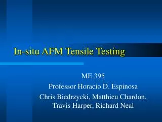
Tensile testing of an as-cast copper alloy. Steps in the process. Marking the gauge length Loading the specimen Zeroing the crosshead Fitting the extensometer Proof stress measurement Plastic deformation and fracture The load/extension curve The fracture surface Measuring ductility.

E N D
Steps in the process • Marking the gauge length • Loading the specimen • Zeroing the crosshead • Fitting the extensometer • Proof stress measurement • Plastic deformation and fracture • The load/extension curve • The fracture surface • Measuring ductility
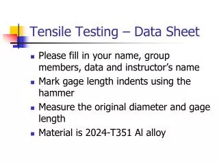
Marking the gauge length • In order to be able to measure the DUCTILITY of the metal, we must first mark a measured gauge length on the sample. • This is done by coating the test sample with lacquer, and then scratching two circumferential marks in the lacquer 70mm apart. • [We must also measure the diameter of the test sample so we can calculate its area of cross section.]
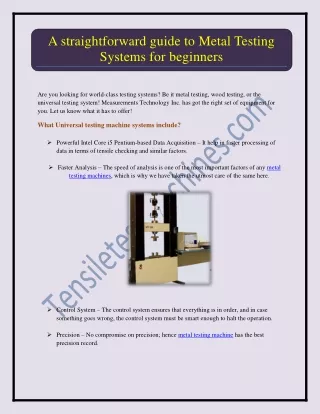
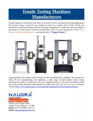
Loading the specimen • Once the sample has been measured, it is loaded into the tensile testing machine. • Special split collars grip the head of the sample. • The collars are held inside cylindrical grips which are free to pivot in the vertical plane. • This allows the sample freedom to align itself once the grips begin to move apart.
Zeroing the cross-head • At the moment, no load or force is being applied to the sample. • The bottom crosshead is lowered until all the slackness is removed and the grips are about to begin to pull on the sample. • The sample is almost ready for testing.
Fitting the extensometer • An extensometer is attached to the gauge length of the sample. • The extensometer grips the sample and measures how much the sample is being stretched as the tensile forces on the sample are increased. • It therefore allows us to measure very accurately the extension on the sample as the load is increased.
Proof stress measurement • As a tensile force is applied, the metal stretches elastically at first. • The computer plots the load on the sample (in kN on the y axis) versus the extension of the metal (in mm on the x axis). • Lines show the force required to extend the sample by 0.1% (Rp1) and 0.2% (Rp2). This allows us to calculate the 0.1% proof stress and 0.2% proof stress for the sample.
Proof stress calculation • 0.1% proof stress = load to cause 0.1% extension Cross sectional area of the sample
Plastic deformation & fracture • Once the sample has been stretched beyond the proof stress, force on the sample is so large that the strain in the sample becomes permanent. • The sample can now break at any time, perhaps without warning. This would damage the extensometer, so the next step is to remove it from the sample. • The load on the sample continues to increase until it is large enough to break the metal.
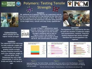
The load vs extension curve • The final load versus extension curve shows an initial stage where the gradient of the line is constant. Here doubling the load doubles the extension, and the sample behaves elastically. • In the second stage, the line begins to flatten off. Here the metal is being permanently stretched (or plastically deformed). [However, note that it requires an ever greater load to keep stretching the sample. The metal therefore gets harder and stronger as it is stretched. This phenomenon is called work hardening.]
The fracture surface • It is always a good idea to look at the fracture surface of the sample to see if there was a defect inside the metal which may have affected the measured strength of the metal.
Measuring ductility • We now wish to measure how far the sample stretched before it broke (its ‘ductility’). • To do this we put the two broken pieces back together. • We then re-measure the distance between the circumferential scratches in the lacquer on the gauge length of the sample.
The final extension • The distance between the marks on the gauge length at the end of the test is 79mm. • This gives an elongation to fracture of 13%.
Calculating % elongation • Elongation to fracture = Final length – initial length x 100 Initial length