TGah Efficient TIM Encoding
TGah Efficient TIM Encoding. Authors:. Date: 2012-05-14. Authors:. TIM element in STD 802.11 - 2012 Supports up to 2007 STAs (2008 AIDs) Contains the entire traffic indication bitmap Inefficient to encode a low density bitmap 802.11ah requirements

TGah Efficient TIM Encoding
E N D
Presentation Transcript
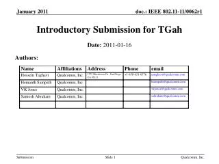
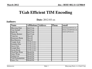
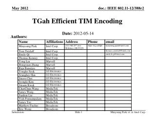
TGah Efficient TIM Encoding Authors: Date:2012-05-14 Minyoung Park, et. al. Intel Corp.
Authors: Minyoung Park, Intel Corp.
TIM element in STD 802.11 - 2012 • Supports up to 2007 STAs (2008 AIDs) • Contains the entire traffic indication bitmap • Inefficient to encode a low density bitmap • 802.11ah requirements • Need to support more than 2007 STAs (e.g. 6000 STAs) [1] • Need to support two very different use cases [2] • Sensor use case: low duty-cycle, Extended Wi-Fi use case: high duty-cycle • One beacon interval can support only limited number of STAs (e.g. < 100 STAs) • Low density bitmap for a large number of associated STAs • TIM has to be encoded efficiently to minimize channel occupancy (overhead) • TGah data rates are much lower than 802.11a/b/g/n/ac • In this presentation, an efficient TIM encoding scheme is proposed Introduction Minyoung Park, et. al. Intel Corp.
802.11 STD Partial Virtual Bitmap Encoding • “… the Partial Virtual Bitmap field consists of octets numbered N1 to N2 of the traffic indication virtual bitmap, where N1 is the largest even number such that bits numbered 1 to (N1 × 8) – 1 in the bitmap are all 0 and N2 is the smallest number such that bits numbered (N2 + 1) × 8 to 2007 in the bitmap are all 0. • Example: • AID=6, AID=20, AID=45, AID=108, and AID = 1010 bits set to 1 • 5 AIDs are encoded into 127 bytes Partial Virtual Bitmap • Current TIM encoding is inefficientfor a low density bitmap*. *) Bitmap density = number of paged stations/number of associated stations Current 802.11 STD Partial Virtual Bitmap Encoding - Example Traffic Indication Bitmap (total 251 Bytes) Encoded Partial Virtual Bitmap = 127 bytes Minyoung Park, et. al. Intel Corp.
Basic idea: • Divide the total AID space into small blocks in a hierarchical manner and transmit only the blocks with non-zero values • Easier to break a large TIM into small groups of STAs and easier to maintain • Different classes of STAs can be easily grouped into different groups/pages (e.g. Sensor STAs in Page 1 and Offloading STAs in Page 2) • Three level hierarchy: Page/Block/Sub-Block Proposed Hierarchical Structure of Traffic Indication Map Supporting max TBD STAs (e.g. 8192) Page 1 Page 2 Page 3 Page 4 NP (e.g. 4) Pages: 2048 STAs … NB (e.g. 32) Blocks: Block1 Block2 Block3 Block4 Block5 Block6 Block7 Block8 Block31 Block32 64 STAs 8 Sub-blocks: 1 octet = 8 STAs Minyoung Park, et. al. Intel Corp.
Based on the hierarchical structure of the traffic bitmap in the previous slide, the association identifier (AID) structure is maintained as below • STAs are grouped into Pages, Blocks, Sub-Blocks AID Structure The number of Pages and Blocks are variable Minyoung Park, et. al. Intel Corp.
Partial Virtual Bitmap is encoded in Block level • Partial virtual bitmap consists of one or more encoded Blocks of a single Page • Block encoding: • Block Control(3 bits) + Block Offset (5 bits) + Block Bitmap (1octet) + Sub-Block Bitmaps (0-8octets) • Block Control field: controls how the Block Bitmap and the Sub-Block Bitmap fields are used • Block bitmap encoding: AID = [Page Index(2b), Block Offset(5b), n(3b), m(3b)] • The n-th bit position of the Block Bitmap indicates whether the n-th Sub-Block Bitmap is present in the Sub-Block field • The m-th bit position of the Sub-Block Bitmap indicates whether the m-th STA has data buffered at the AP • Single AID: AID = [Page Index(2b), Block Offset(5b), Block Bitmap[5:0]] • When there is a single AID in a Block, 6 bits of the Block Bitmap field is used to indicate the 6 LSBs of the AID • The Sub-Block field is not present • Inverse bitmap: if there are many 1s in the bitmap of a Block, inverse the bitmap and encode the inversed bitmap • Can expect many cases where STAs sleep for a long period of time TIM Encoding Propsal - Block level encoding Bitmap Control Partial Virtual Bitmap … Block L Block M Block P Block Control field: Block Bitmap Single AID ‘Offset+Length+Bitmap’ + Inverse bitmap Bitmap Control (1 octet) 1 octet 0-8 octets 1 octet Page Index TBD Block Control Block Offset Block Bitmap Sub-Blocks (variable) 2 bits 5 bits 3 bits 1 octet … Sub-Block Bitmap M Sub-Block Bitmap 1 Sub-Block Bitmap 2 Minyoung Park, et. al. Intel Corp.
‘Offset+Length+Bitmap’ mode: encodes more than 8 Sub-Block Bitmaps. • The Block Bitmap field is used to indicate the length of Sub-Block Bitmaps following the Block Bitmap field. • AID = [Page Index (2b), Block Offset(5b),zeros(6b)]+ p, the p-th bit position of the Sub-Block Bitmap field indicates whether the p-th STA has data buffered at the AP. • This mode is used when more than 8 contiguous Sub-Blocks are transmitted. Offset+Length+Bitmap (OLB) Bitmap Control Partial Virtual Bitmap … Block p Block v Block n Block n+1 Block n+m … Bitmap Control (1 octet) 2 octets L octets Page Index OLB mode TBD Block Control Block Offset Length (L) L Sub-Block Bitmaps 2 bits 3 bits 5 bits 1 octet Minyoung Park, et. al. Intel Corp.
Block Bitmap encoding • Block offset(5b) + Block ctrl(3b) + Block bitmap(1 octet) + Sub-block bitmap (0-8 octets) • Example bitmap: • Total encoded length = 5 bytes 1. Block Bitmap mode Block 1 Sub-block3 Sub-block7 Sub-block1 Traffic indication bitmap: 0010 1001 0000 0000 1001 0001 0000 0000 0000 0000 0000 0000 0001 0000 0000 0000 AID=51 ( 00 00000 110 011) Block bitmap Block offset Block Ctrl (3b) Encoded bitmap Block Bitmap 00000 1010 0010 0010 1001 1001 0001 0001 0000 Sub-block Bitmap 1 Sub-block Bitmap 3 Sub-block Bitmap 7 n-th bit position indicatespresence of n-th Sub-block Minyoung Park, et. al. Intel Corp.
Single AID mode • Block offset (5b) + Block ctrl(3b) + last 6 bits of an AID • Example bitmap: • Encoded bitmap: • Total encoded length = 2 bytes 2. Single AID mode Block 1 Sub-block3 Sub-block7 Sub-block1 Traffic indication bitmap: 0000 0000 0000 0000 0000 0000 0000 0000 0000 0000 0000 0000 0001 0000 0000 0000 AID=51 ( 00 00000 110 011) 6 LSBs ofthe AID Block bitmap Block Offset (5b) Block Ctrl (3b) Single AID mode 00000 110011 00 6 LSBs ofthe AID Minyoung Park, et. al. Intel Corp.
Block bitmap + Inverse mode • Block offset(5b) + Block ctrl(3b) + Block bitmap(1 octet) + Sub-block bitmaps (0-8 octets) • Example bitmap: • Total encoded length = 4 bytes • Decoding is simply the reverse procedure of the encoding 3. Inverse Bitmap mode Block 1 Sub-block7 Sub-block1 Traffic indication bitmap: 0010 1001 1111 1111 1111 1111 1111 1111 1111 1111 1111 1111 0001 1111 1111 1111 Inverse the bitmap 1101 0110 0000 0000 0000 0000 0000 0000 0000 0000 0000 0000 1110 0000 0000 0000 Block Offset(5b) Block Bitmap Block Ctrl (3bits) Encoded bitmap 00000 Block Bitmap +Inverse 1000 0010 1101 0110 1110 0000 Sub-block Bitmap 1 Sub-block Bitmap 7 n-th bit position indicatespresence of n-th Sub-block Minyoung Park, et. al. Intel Corp.
Offset+Length+Bitmap mode • Block offset(5b) + Block ctrl(3b) + Length(8b) + Sub-block Bitmaps • Total encoded length = 16 bytes 4. OLB mode Traffic indication bitmap: Sub-block1 Sub-block8 Block#0 0010 1001 0100 1010 1001 0001 0110 1001 1010 1011 0111 0101 0001 0000 0010 0001 Block#1 1001 0001 0001 0000 0010 0001 0001 0000 0010 0001 1010 1011 0000 0000 0000 0000 Block bitmap Block offset Block Ctrl (3bits) Encoded bitmap Offset+Length+Bitmap mode Length=14 00000 0010 1001 0100 1010 1001 0001 0110 1001 1010 1011 0111 0101 0001 0000 0010 0001 Indicates the length of the Sub-Block bitmaps 1001 0001 0001 0000 0010 0001 0001 0000 0010 0001 1010 1011 Minyoung Park, et. al. Intel Corp.
Compression Comparison (1) • Scenario 1: 126 STAs • 126 STAs associated with AP • X axis indicates the number of paged STAs • randomly distributed AIDs in [1:126] • Averaged over 200 iterations • Y axis represents the size of the compressed bitmap • Curves • Hierarchy: Block level compression with inverse encoding • Hierarchy + OLB: Block level compression with ‘Offset + Bitmap + Length’ mode (indicated as ‘Adaptive’ in Y-axis) • STD-VTIM: Standard virtual TIM map • Including OLB mode helps reduce TIM length in mid-density region of the map by up to 10%. • Compression performance of Hierarchy+OLB is the best in all TIM map densities Minyoung Park, et. al. Intel Corp.
Compression Comparison (2) • Scenario 1: 256 STAs • 256 STAs associated with AP • X axis indicates the number of paged STAs • randomly distributed AIDs in [1:256] • Averaged over 200 iterations • Y axis represents the size of the compressed bitmap • Curves • Hierarchy: Block level compression with inverse encoding • Hierarchy + OLB: Block level compression with ‘Offset + Bitmap + Length’ mode (indicated as ‘Adaptive’ in Y-axis). • STD-VTIM: Standard virtual TIM map • Including OLB mode helps reduce TIM length in mid-density region of the map by more than 14%. • Compression performance of Hierarchy+OLB is the best in all TIM map densities Minyoung Park, et. al. Intel Corp.
Compression Comparison (3) • Scenario 1: 512 STAs • 512 STAs associated with AP • X axis indicates the number of paged STAs • randomly distributed AIDs in [1:512] • Averaged over 200 iterations • Y axis represents the size of the compressed bitmap • Curves • Hierarchy: Block level compression with inverse encoding • Hierarchy + OLB: Block level compression with ‘Offset + Bitmap + Length’ mode (indicated as ‘Adaptive’ in Y-axis) • STD-VTIM: Standard virtual TIM map • Including OLB mode helps reduce TIM length in mid-density region of the map by more than 16%. • Compression performance of Hierarchy+OLB is the best in all TIM map densities Minyoung Park, et. al. Intel Corp.
Compression Comparison (4) • Scenario 1: 1024 STAs • 1024 STAs associated with AP • X axis indicates the number of paged STAs • randomly distributed AIDs in [1:1024] • Averaged over 200 iterations • Y axis represents the size of the compressed bitmap • Curves • Hierarchy: Block level compression with inverse encoding • Hierarchy + OLB: Block level compression with ‘Offset + Bitmap + Length’ mode (indicated as ‘Adaptive’ in Y-axis) • STD-VTIM: Standard virtual TIM map • Including OLB mode helps reduce TIM length in mid-density region of the map by more than 18%. • Compression performance of Hierarchy+OLB is the best in all TIM map densities Minyoung Park, et. al. Intel Corp.
We proposed • Hierarchical structure of TIM and AID structure • Good for grouping and maintaining different types of STAs • Good for dividing a large size bitmap into smaller size TIM elements • Block level TIM encoding • Good encoding for a wide range of number of STAs • Good for realistic scenarios where limited number of STAs are paged in a single TIM (i.e. the number of paged STAs < 100) • Up to 30-98% smaller encoded bitmap size compared to the current 802.11 STD for the realistic scenarios • Compression performance of Hierarchy+OLB is the best in all TIM map densities Summary Minyoung Park, et. al. Intel Corp.
Do you support the hierarchical structure of the traffic indication map shown in Slide 5 and the AID structure shown in Slide 6? • Y: • N: • A: Straw Poll 1 Minyoung Park, et. al. Intel Corp.
Do you support the Block-level TIM encoding outlined in Slide 7-8? • Y: • N: • A: Straw Poll 2 Minyoung Park, et. al. Intel Corp.
Move to accept the hierarchical structure of the traffic indication map shown in Slide 5 and the AID structure shown in Slide 6 in the TGah Specification Framework document. • Y: • N: • A: Motion 1 Minyoung Park, et. al. Intel Corp.
Move to accept the Block-level TIM encoding outlined in Slide 7-8 in the TGah Specification Framework document. • Y: • N: • A: Motion 2 Minyoung Park, et. al. Intel Corp.
[1] 11/11-905r3 “TGah Functional Requirements and Evaluation Methodology.” [2] Rolf de Vegt, “Potential Compromise for 802.11ah Use Case Document,” 11-11/457r0. References Minyoung Park, et. al. Intel Corp.
Backup Minyoung Park, et. al. Intel Corp.
The number of Pages and the number of Blocks depend on how the 7 MSBs of an AID is interpreted Variable Number of Pages and Blocks 64 STAs … Blocks: 1 8 9 16 17 24 25 32 4x32 4 Blocks / Page (32 Pages in total) 8 Blocks / Page (16 Pages in total) 16 Blocks / Page (8 Pages in total) 32 Blocks / Page (4 Pages in total) Minyoung Park, et. al. Intel Corp.
STAs supporting different use cases can be easily grouped into different Pages • Example: • Sensor stations Page 1 • A large number of STAs, infrequent down-link traffic • Offloading stations Page 2 • A small number of STAs, frequent down-link traffic Grouping DTIM Beacon (Page1,Page2) DTIM Beacon (Page1,Page2) TIM Beacon (Page2) TIM Beacon (Page2) TIM Beacon (Page2) TIM Beacon (Page2) Minyoung Park, et. al. Intel Corp.
Parameters: • Nasta STAs associated with an AP • Nasta = 64, 256, 512,1024, 2048, and 8192 • X-axis indicates the number of paged STAs (Npsta) • The paged STAs randomly distributed in the bitmap [1:Nasta] • Averaged over 500 iterations • Y-axis represents the size of the encoded bitmap in bits • Performance comparison • STD-VTIM: the current 802.11 standard virtual TIM encoding scheme including 2 byte offset • Proposed: the proposed Block encoding scheme with Inverse bitmap mode applied Simulation Setup Minyoung Park, et. al. Intel Corp.
Nasta = 64 • The proposed encoding is better than or very close to STD-VTIM • Up to 30% better encoding (Npsta<20, bitmap density < 30%) • Up to 78% better encoding (Npsta>45, bitmap density > 70%) Results - Scenario 1 Minyoung Park, et. al. Intel Corp.
Nasta = 256 • The proposed encoding is better for Npsta <45 (bitmap density < 18%) • Up to 68% better encoding (Npsta<45) • Not likely to have a large number of STAs (e.g. > 100 STAs) be paged in a single TIM Results - Scenario 2 Minyoung Park, et. al. Intel Corp.
Nasta = 512 • The proposed encoding is better for Npsta <85 (bitmap density < 17%) • Up to 80% better encoding (Npsta<85) • Not likely to have >100 STAs be paged in a single TIM Results - Scenario 3 Minyoung Park, et. al. Intel Corp.
Nasta=1024 • The proposed encoding is better for Npsta <165 (bitmap density<17%) • Up to 90% better encoding (Npsta<165) • Not likely to have >100 STAs be paged in a single TIM Results - Scenario 4 Minyoung Park, et. al. Intel Corp.
Nasta = 2048 • The proposed encoding is better for Npsta <330 (bitmap density<16%) • Up to 95% better encoding (Npsta<330) • Not likely to have >100 STAs be paged in a single TIM Results - Scenario 5 Minyoung Park, et. al. Intel Corp.
Nasta = 8192 • The proposed encoding is better for Npsta <1300 (bitmap density < 16%) • Up to 98% better encoding (Npsta<1300) • Not likely to have >100 STAs be paged in a single TIM Results - Scenario 6 Minyoung Park, et. al. Intel Corp.