Download

1 / 42
420 likes | 621 Views
Experiment 3. Part A: Making an Inductor Part B: Measurement of Inductance Part C: Simulation of a Transformer Part D: Making a Transformer. Inductors & Transformers. How do transformers work? How to make an inductor? How to measure inductance? How to make a transformer?. ?. Part A.

E N D
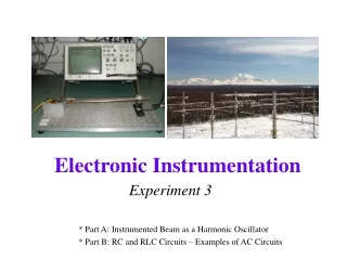
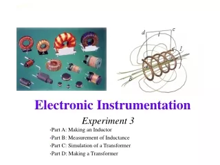
Experiment 3 Part A: Making an Inductor Part B: Measurement of Inductance Part C: Simulation of a Transformer Part D: Making a Transformer
Inductors & Transformers • How do transformers work? • How to make an inductor? • How to measure inductance? • How to make a transformer? ? Electronic Instrumentation
Part A • Inductors Review • Calculating Inductance • Calculating Resistance Electronic Instrumentation
Inductors-Review • General form of I-V relationship • For steady-state sine wave excitation Electronic Instrumentation
Determining Inductance • Calculate it from dimensions and material properties • Measure using commercial bridge (expensive device) • Infer inductance from response of a circuit. This latter approach is the cheapest and usually the simplest to apply. Most of the time, we can determine circuit parameters from circuit performance. Electronic Instrumentation
Making an Inductor • For a simple cylindrical inductor (called a solenoid), we wind N turns of wire around a cylindrical form. The inductance is ideally given by where this expression only holds when the length d is very much greater than the diameter 2rc Electronic Instrumentation
Making an Inductor • Note that the constant o = 4 x 10⁻⁷ H/m is required to have inductance in Henries (named after Joseph Henry of Albany) • For magnetic materials, we use instead, which can typically be 105 times larger for materials like iron • is called the permeability Electronic Instrumentation
Some Typical Permeabilities • Air 1.257x10⁻⁶ H/m • Ferrite U M33 9.42x10⁻⁴ H/m • Nickel 7.54x10⁻⁴ H/m • Iron 6.28x10⁻³ H/m • Ferrite T38 1.26x10⁻² H/m • Silicon GO steel 5.03x10⁻² H/m • supermalloy 1.26 H/m Electronic Instrumentation
Making an Inductor • If the coil length is much smaller than the diameter (rwis the wire radius) Such a coil is used in the metal detector at the right Electronic Instrumentation
Calculating Resistance • All wires have some finite resistance. Much of the time, this resistance is negligible when compared with other circuit components. • Resistance of a wire is given by l is the wire length A is the wire cross sectional area (prw2) s is the wire conductivity Electronic Instrumentation
Some Typical Conductivities • Silver 6.17x10⁷ Siemens/m • Copper 5.8x10⁷ S/m • Aluminum 3.72x10⁷ S/m • Iron 1x10⁷ S/m • Sea Water 5 S/m • Fresh Water 25x10-6 S/m • Teflon 1x10-20 S/m Siemen = 1/ohm Electronic Instrumentation
Wire Resistance • Using the Megaconverter at http://www.megaconverter.com/Mega2/ (see course website) Electronic Instrumentation
Part B: Measuring Inductance with a Circuit • For this circuit, a resonance should occur for the parallel combination of the unknown inductor and the known capacitor. If we find this frequency, we can find the inductance. Electronic Instrumentation
Determining Inductance Vin Vout • Reminder—The parallel combination of L and C goes to infinity at resonance. (Assuming R2 is small.) Electronic Instrumentation
Determining Inductance Electronic Instrumentation
Even 1 ohm of resistance in the coil can spoil this response somewhat Coil resistance small Coil resistance of a few Ohms Electronic Instrumentation
Part C • Examples of Transformers • Transformer Equations Electronic Instrumentation
Transformers • Cylinders (solenoids) • Toroids Electronic Instrumentation
Transformer Equations Symbol for transformer Electronic Instrumentation
Deriving Transformer Equations • Note that a transformer has two inductors. One is the primary (source end) and one is the secondary (load end): LS& LL • The inductors work as expected, but they also couple to one another through their mutual inductance: M2=k2 LS LL Electronic Instrumentation
Transformers • Assumption 1: Both Inductor Coils must have similar properties: same coil radius, same core material, and same length. Electronic Instrumentation
Transformers IS IL Note Current Direction • Let the current through the primary be • Let the current through the secondary be • The voltage across the primary inductor is • The voltage across the secondary inductor is Electronic Instrumentation
Transformers • Sum of primary voltages must equal the source • Sum of secondary voltages must equal zero Electronic Instrumentation
Transformers • Assumption 2: The transformer is designed such that the impedances are much larger than any resistance in the circuit. Then, from the second loop equation Electronic Instrumentation
Transformers • k is the coupling coefficient • If k=1, there is perfect coupling. • k is usually a little less than 1 in a good transformer. • Assumption 3: Assume perfect coupling (k=1) We know M2=k2 LS LL= LS LL and Therefore, Electronic Instrumentation
Transformers • The input impedance of the primary winding reflects the load impedance. • It can be determined from the loop equations • 1] • 2] • Divide by 1] IS. Substitute 2] and M into 1] Electronic Instrumentation
Transformers • Find a common denominator and simplify • By Assumption 2, RL is small compared to the impedance of the transformer, so Electronic Instrumentation
Transformers • It can also be shown that the voltages across the primary and secondary terminals of the transformer are related by Note that the coil with more turns has the larger voltage. • Detailed derivation of transformer equations http://hibp.ecse.rpi.edu/~connor/education/transformer_notes.pdf Electronic Instrumentation
Transformer Equations Electronic Instrumentation
Part D • Step-up and Step-down transformers • Build a transformer Electronic Instrumentation
Step-up and Step-down Transformers Step-down Transformer Step-up Transformer Note that power (P=VI) is conserved in both cases. Electronic Instrumentation
Build a Transformer • Wind secondary coil directly over primary coil • “Try” for half the number of turns • At what frequencies does it work as expected with respect to voltage? When is ωL >> R? Electronic Instrumentation
Some Interesting Inductors • Induction Heating Electronic Instrumentation
Some Interesting Inductors • Induction Heating in Aerospace Electronic Instrumentation
Some Interesting Inductors • Induction Forming Electronic Instrumentation
Primary Coil Secondary Coil Some Interesting Inductors • Coin Flipper Electronic Instrumentation
Some Interesting Inductors • GE Genura Light Electronic Instrumentation
Some Interesting Transformers • A huge range in sizes Electronic Instrumentation
Some Interesting Transformers • High Temperature Superconducting Transformer Electronic Instrumentation
Household Power • 7200V transformed to 240V for household use Electronic Instrumentation
Wall Warts Transformer Electronic Instrumentation