Download

1 / 31
310 likes | 338 Views
Learn to program KIPR Link, connect sensors, control motors, and work with analog sensors. Hands-on exercises. Practical guidance by Dr. S. Ahmadi. Charging and Using KIPR Link explained.

E N D
The George Washington University Department of ECE ECE 1010Intro: Electrical & Computer Engineering • Introducing KIPR Link/Interface and Set-up • Continuation of Programming Skills • Connecting KIPR Link • Making sure connections are fine • Introduction to analog sensors Dr. S. Ahmadi Week 2
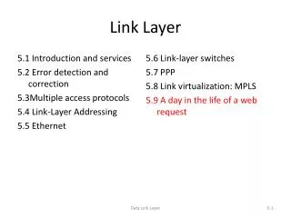
Outline • PART I • Programming Exercises • Connecting KIPR Link • Hands-on Programming • Starting IC Program (Downloading Firmware) • Running Programs • PART II • Introduction to Analog Sensors • Project Description
Hardware Components KIPR Link (Interface to motors & sensors) AC Adapter (Charges the KIPR Link) USB Cable (Connects the KIPR Link to the computer) Micro-USB Plug (Connects to the back of the KIPR Link) USB Plug (Connects to USB port on the computer)
Connecting the KIPR Link • Connect the KIPR Link to the PC using the USB cable. • Start “KISS IDE” on the PC.
Go to Start All Programs KISS Platform 5.2.2 KISS IDE 5.2.2
Overview of Interaction Window Compile and download program to KIPR Link Run code
Connecting to the KIPR Link Select the COM port to which your KIPR Link is connected to and click OK.
BASIC HANDYBOARD HOOKUP PROCEDURE • Connect KIPR Link to computer. • Turn KIPR Link on. • Open the KISS IDE software. Make sure the computer is talking to the controller. • After connecting KIPR Link, compile and run the “Hello, World!” program. • If you see “Hello, World!” printed on the KIPR Link’s display, your connections are correct.
Sample Beeping Program /* Program to beep 20 times continuously. */ int main() { int count=0; while(count<=20) { tone(1000, 0.5); count=count+1; // Incrementing counter } return 0; } • Extra: Wait half a second between beeps.
Motor control commands • DC motor control commands • fd(n); Rotate motor ‘n’ forward • bk(n); Rotate motor ‘n’ backwards. • motor(n, s); move motor ‘n’ at speed ‘s’ • ‘s’ range: -100 ~ +100 • ‘s’>0 forward • ‘s’<0 reverse • off(n); turn off motor ‘n’ • ao(); turn off all motors
Motor Exercise Procedure • Attach the two motors to the connector wires. Next, attach the wire plugs to KIPR Link ports. • Turn the KIPR Link on. • Open KISS IDE software. Make sure the computer is talking to the controller. • Turn on motor 1 using the motor(n,x) command. • Make motor 1 alternate between a forward and backward direction. • You can change the speed of your motors. For example motor(1,100) means motor 1 is turning at 100 or full speed.
Motor Control: Exercise #1 • Exercise #1: Motor speed control • write IC program to run one motor in three different speeds. • Turn motor #1 on • drive in slow speed for 3 seconds • drive in medium speed for 5 seconds • drive in high speed for 3 seconds • Stop motor
Sample Motor Program (Exercise #2) int main() {printf("Press START to test motors\n"); while(a_button() == 0); //wait until side button is pressedfd(1); // Motor in port 1 go forward sleep(2.0); // Sleep for 2 seconds.bk(1); // Motor in port 1 go backward sleep(2.0);off(1); // Turn motor in port 1 off fd(3); // Motor in port 3 go forward sleep(2.0);bk(3); // Motor in port 3 go backward sleep(2.0);off(3); return 0; }
Charging The KIPR Link • Charging the KIPR Link takes about 1.5 hours, after which it can be left in the power indefinitely. • Note: Students will be responsible for charging their groups KIPR Link.
SUMMARY of Main Functions from Week 2 • fd(int n); Rotate motor ‘n’ forward • bk(int n); Rotate motor ‘n’ backwards. • motor(int n, int s); move motor ‘n’ at speed ‘s’ • ‘s’ range: -100 ~ +100 • ‘s’ > 0 – motor moves forward • ‘s’ < 0 – motor reverses/moves backward • off(int n); turn off motor ‘n’ • ao(); turn off all motors • sleep(int x); // Delays execution of next statement for ‘x’ secs. • msleep(int x); // Delays execution of next statement for ‘x’ msecs • tone(float freq, float length); // Causes the handy-board to beep
Analog Sensors • Outputs a range of integer values. • Range depends on the signal being sensed. • The analog ports are ports 0 – 7. • Actual ports that should be used will depend on the sensor being used. • The three main analog sensors that we will be using are the Light Sensor, the Optical Rangefinder Sensor and the Infrared Sensor. • In today’s project, only the Optical Rangefinder will be utilized.
Analog Sensor 1: Light Sensor • The light sensor included in the kit, can “sense” lightness and darkness. • Connect to analog ports 0-7 • Access with function analog10(port#) • Analog values range from 0 - 1023. • A low value indicates bright light or close proximity to a light source • A high value indicates dark light or far proximity from a light source Enlarged Light Sensor
Analog Sensor 2: IR Reflectance Sensor “Top Hat” • The IR sensor included in the kit, can also “sense” lightness and darkness like the light sensor • Connect to analog ports 0-7 • Access with function analog10(port#) • Low values indicate bright light, light color, or close proximity • High values indicate low light, dark color, or distance of several inches • Sensor has a reflectance range of about 3 inches Enlarged IR Sensor
Light Sensor Sample Code /* Program that measures the reads from the light sensor and displays its output values continuously. */ int main() { int color=0; printf(“\n Light Sensor Sample Program"); while(!a_button()); // Press Start Button while(1) // Continue infinitely { msleep(500); color = analog10(0); // Read “lower deck” analog port 0 printf(“\n Color is %d”, color); // if near 0 – WHITE // if near 1023 - BLACK } return 0; }
Project Description • The aim of this project is to design a robot that moves along a given path, from the Start point, towards the Finish line. • The thick black line acts as the guide for the robot to follow. • As an optional element to the project, after reaching the finish line, the robot should turn around, and go back along the path it came to the starting point. • Robot will be judged on smoothness of journey, and robot design. • It is the students’ responsibility to make sure that the Handy Board is fully charged • Each group will have one chance to demonstrate their project to the judges. Therefore, fully test your project before demonstration.
Project #1 - Route 2m 2m Finish Start 2m 2m