CURRENT ELECTRICITY - I
150 likes | 347 Views
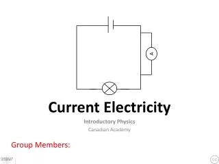
CURRENT ELECTRICITY - I. Electric Current Conventional Current 3. Drift Velocity of electrons and current 4. Current Density 5. Ohm’s Law 6. Resistance, Resistivity, Conductance & Conductivity 7. Temperature dependence of resistance 8. Colour Codes for Carbon Resistors

CURRENT ELECTRICITY - I
E N D
Presentation Transcript
CURRENT ELECTRICITY - I • Electric Current • Conventional Current • 3. Drift Velocity of electrons and current • 4. Current Density • 5.Ohm’s Law • 6. Resistance, Resistivity, Conductance & Conductivity • 7. Temperature dependence of resistance • 8. Colour Codes for Carbon Resistors • Series and Parallel combination of resistors • 10. EMF and Potential Difference of a cell • 11. Internal Resistance of a cell • 12. Series and Parallel combination of cells
b I c a d 0 t Electric Current: The electric current is defined as the charge flowing through any section of the conductor in one second. I = q / t (if the rate of flow of charge is steady) I = dq / dt (if the rate of flow of charge varies with time) Different types of current: • Steady current which does not vary with time b)&c)Varying current whose magnitude varies with time d) Alternating current whose magnitude varies continuously and direction changes periodically
++++ ++++ - - - - - - - - + + + I - - - I vd l E - - - I = neA vd I vd = a τ vd = - (eE / m) τ vd - drift velocity, a – acceleration, τ – relaxation time, E – electric field, e – electronic charge, m – mass of electron, n – number density of electrons, l – length of the conductor and A – Area of cross-section Conventional Current: Conventional current is the current whose direction is along the direction of the motion of positive charge under the action of electric field. Conventional current due to motion of electrons is in the direction opposite to that of motion of electrons. Drift Velocity and Current: Drift velocity is defined as the velocity with which the free electrons get drifted towards the positive terminal under the effect of the applied electric field. A Current is directly proportional to drift velocity.
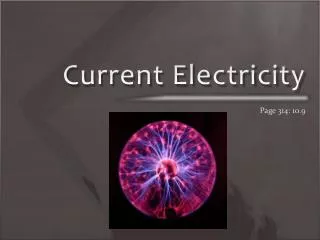
J = I / A = nevd In vector form, I = J . A I V I 0 V Currentdensity: Current density at a point, within a conductor, is the current through a unit area of the conductor, around that point, provided the area is perpendicular to the direction of flow of current at that point. Ohm’s Law: The electric current flowing through a conductor is directly proportional to the potential difference across the two ends of the conductor when physical conditions such as temperature, mechanical strain, etc. remain the same. I α VorV α IorV = R I
I = neA | vd| I = neA (e |E| / m) τ ne2Aτ V I = m l ml V = m I ne2Aτ whereρ = m l l ne2τ R = R = ρ ne2τ A is resistivity or specific resistance A Resistance: The resistance of conductor is the opposition offered by the conductor to the flow of electric current through it. R = V/I Resistance in terms of physical features of the conductor: Resistance is directly proportional to length and inversely proportional to cross-sectional area of the conductor and depends on nature of material. Resistivity depends upon nature of material and not on the geometrical dimensions of the conductor.
m l R = R2 – R1 Rt – R0 ne2τ A α= α= R1t2 – R2t1 R0 t Relations between vd , ρ, l, E, J and V: When temperature increases, vd decreases and ρ increases. When lincreases, vd decreases. ρ = E / J = E / nevd vd = E /(neρ) vd = V /(neρl) (since, J = I / A = nevd ) (since, E = V / l ) Conductance and conductivity: Conductance is the reciprocal of resistance. Its S.I unit is mho. Conductivity is the reciprocal of resistivity. Its S.I unit is mho / m. Temperature dependence of Resistances: When temperature increases, the no. of collisions increases due to more internal energy and relaxation time decreases. Therefore, Resistance increases. Temperature coefficient of Resistance: R0 – Resistance at 0°C Rt – Resistance at t°C R1 – Resistance at t1°C R2 – Resistance at t2°C or If R2 < R1, then α is – ve.
Colour code for carbon resistors: BV BGold BV B GRB Silver The first two rings from the end give the first two significant figures of resistance in ohm. The third ring indicates the decimal multiplier. The last ring indicates the tolerance in per cent about the indicated value. Eg. AB x 10C ±D %ohm 17 x 100 = 17 ± 5% Ω 52 x 106± 10% Ω 17 x 100 = 17 ± 20%Ω B B ROY of Great Britain has Very Good Wife
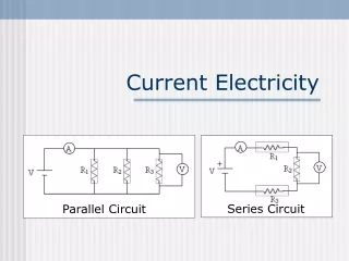
Red Ends Gold Ring Yellow Body Blue Dot R1 R2 R3 R1 R2 R3 Another Colour code for carbon resistors: • The colour of the body gives the first significant figure. • The colour of the ends gives the second significant figure. • The colour of the dot gives the decimal multipier. • iv) The colour of the ring gives the tolerance. YRBGold 42 x 106 ± 5% Ω Series combination of resistors: R = R1 + R2 + R3 R is greater than the greatest of all. Parallel combination of resistors: 1/R =1/R1 + 1/R2 + 1/R3 R is smaller than the smallest of all.
Sources of emf: The electro motive force is the maximum potential difference between the two electrodes of the cell when no current is drawn from the cell. Comparison of EMF and P.D:
E = V + v = IR + Ir = I (R + r) I = E / (R + r) This relation is called circuit equation. E r I I R V Internal Resistance of a cell: The opposition offered by the electrolyte of the cell to the flow of electric current through it is called the internal resistance of the cell. Factors affecting Internal Resistance of a cell: • Larger the separation between the electrodes of the cell, more the length of the electrolyte through which current has to flow and consequently a higher value of internal resistance. • Greater the conductivity of the electrolyte, lesser is the internal resistance of the cell. i.e. internal resistance depends on the nature of the electrolyte. • The internal resistance of a cell is inversely proportional to the common area of the electrodes dipping in the electrolyte. • The internal resistance of a cell depends on the nature of the electrodes. v
E r v E = V + v = V + Ir Ir = E - V Dividing by IR = V, Ir E – V = IR V I I R V E r = ( - 1) R V V V + + r r I I R.B (R) K R.B (R) K Internal Resistance of a cell in terms of E,V and R: Determination of Internal Resistance of a cell by voltmeter method: Open circuit (No current is drawn) EMF (E) is measured Closed circuit (Current is drawn) Potential Difference (V) is measured
I I R V E E E r r r • If R << nr, then I = E / r (ii) If nr << R, then I = n (E / R) nE Current I = nr + R Cells in Series combination: Cells are connected in series when they are joined end to end so that the same quantity of electricity must flow through each cell. • NOTE: • The emf of the battery is the sum of the individual emfs • The current in each cell is the same and is identical with the current in the entire arrangement. • The total internal resistance of the battery is the sum of the individual internal resistances. Total emf of the battery = nE (for n no. of identical cells) Total Internal resistance of the battery = nr Total resistance of the circuit = nr + R Conclusion: When internal resistance is negligible in comparison to the external resistance, then the cells are connected in series to get maximum current.
I I R V E E E r r r • If R << r/n, then I = n(E / r) (ii) If r/n << R, then I = E / R nE Current I = nR + r Cells in Parallel combination: Cells are said to be connected in parallel when they are joined positive to positive and negative to negative such that current is divided between the cells. • NOTE: • The emf of the battery is the same as that of a single cell. • The current in the external circuit is divided equally among the cells. • The reciprocal of the total internal resistance is the sum of the reciprocals of the individual internal resistances. Total emf of the battery = E Total Internal resistance of the battery = r / n Total resistance of the circuit = (r / n) + R Conclusion: When external resistance is negligible in comparison to the internal resistance, then the cells are connected in parallel to get maximum current.