Download
1 / 4
40 likes | 59 Views
Step-up transformers easily transform generated alternating current voltages into much higher voltages, which are then distributed across vast distances via a grid of pylons and cables. The reason for increasing the voltage is that higher distribution voltages imply lower copper losses (I2 R) along the networked grid of cables.

E N D
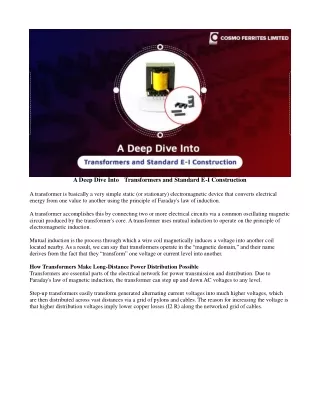
A Deep Dive Into Transformers and Standard E-I Construction A transformer is basically a very simple static (or stationary) electromagnetic device that converts electrical energy from one value to another using the principle of Faraday's law of induction. A transformer accomplishes this by connecting two or more electrical circuits via a common oscillating magnetic circuit produced by the transformer's core. A transformer uses mutual induction to operate on the principle of electromagnetic induction. Mutual induction is the process through which a wire coil magnetically induces a voltage into another coil located nearby. As a result, we can say that transformers operate in the “magnetic domain,” and their name derives from the fact that they “transform” one voltage or current level into another. How Transformers Make Long-Distance Power Distribution Possible Transformers are essential parts of the electrical network for power transmission and distribution. Due to Faraday's law of magnetic induction, the transformer can step up and down AC voltages to any level. Step-up transformers easily transform generated alternating current voltages into much higher voltages, which are then distributed across vast distances via a grid of pylons and cables. The reason for increasing the voltage is that higher distribution voltages imply lower copper losses (I2 R) along the networked grid of cables.
The higher alternating current transmission voltage is then reduced to a much lower, safer, and usable voltage at its destination, where it can power electrical equipment in our homes and workplaces. Working Principles of a Transformer A transformer is a static electrical device that transfers alternating current (AC) from one circuit to another with no change in frequency. Transformers are generally used in electric power applications to increase or decrease the voltages of alternating current. A single-phase voltage transformer is made up of two wire coils, one called the primary winding and the other the secondary winding. The primary side of a transformer is the side that receives power, while the secondary side is the side which delivers power. The primary side of a single-phase voltage transformer is usually the side with the higher voltage. These two coils are not electrically connected to each other; instead, they are wrapped around a common closed magnetic iron circuit known as the core. The two coil windings are magnetically connected by a common core, allowing electrical power to be transferred from one coil to the other. This soft iron core is made up of individual laminations that are assembled together to form the core structure instead of being solid. A single-phase transformer can increase or decrease the voltage applied to the primary winding. A step-up transformer is one that is used to increase the voltage on its secondary winding in relation to the primary winding. A step-down transformer is one that is used to reduce the voltage on the secondary winding in relation to the primary winding.
Primary current- When connected to an electrical source, the primary winding generates magnetic flux in the core. Secondary winding – generates secondary current from magnetic flux in the core. Transformer core – provides a low-resistance path for magnetic flux to flow from the primary winding to the secondary winding, resulting in a closed magnetic circuit. The energy efficiency of a transformer is determined by core losses and copper losses within the transformer. The loss of the core is proportional to the voltage, while the loss of the copper is proportional to the current. The magnetic properties of the core material and core construction determine core loss, which is further subdivided into hysteresis loss and eddy current loss. Most transformers designed for use in homes or offices use one of two types of transformers. They can be constructed with an E-I laminate or a toroidal core.
Standard E-I Transformer Construction The matching “E” and “I” components in an E-I structure are stamped from sheets of thin grain-oriented electrical steel, which are then stacked to form the core. Bobbins are used to wind the primary and secondary windings. To apply the windings, multiple bobbins are placed on spindles and spun. This bobbin method allows for automation, which reduces manufacturing times while also providing insulation between the windings and the core. To complete the transformer, the E-I core laminations are stacked inside the bobbins. Because of their ease of construction, standard E-I transformers are very cost effective to manufacture, which is their primary advantage. Standard E-I transformers, while inexpensive to produce, have several limitations. Small imperfections and burrs in the butting edges of laminations create an effective "air gap" that reduces the operating flux levels as the punched laminations are stacked to form the core structure. With linear construction, winding decoupling is more common, and as a result, leakage inductance and stray capacitance are naturally higher. Furthermore, the loose laminations will vibrate at the fundamental frequency, introducing a disturbing hum (mechanical noise). All of these disadvantages result in a larger transformer with lower efficiency. Conclusion Without electrical transformers, our modern world of efficient power distribution across cities and continents would not be possible. Standard E-I construction is a cost-effective solution for many power conversion needs, but it has drawbacks in terms of size, weight, and efficiency. In the next instalment of our toroidal transformer series, we'll look at how toroidal transformers are made and how they outperform standard E-I construction in terms of performance.