Download
1 / 10
100 likes | 167 Views
Understand the flow of image data processing in MDP, data compression techniques, command lines, error handling, and management of time clock in the EIS/Solar-B system. Details on data lines, compression, commands, error counter-plans, and clock management.

E N D
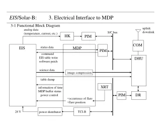
image compression XRT power distributor EIS/Solar-B: 3. Electrical Interface to MDP 3-1 Functional Block Diagram uplink downlink analog data (temperature, current, etc.) S/C bus HK PIM COM status data EIS MDP PIM command EIS table write software patch DHU science data table dump information of time MDP buffer status power control PIM DR ・occurrence of flare ・flare position 28 V TCI-B
EIS MDP DATA CLOCK GATE Normal RS-422 1 MHz HS-26C31 HS-26C32 MDP BUFFER STATUS low-power RS-422 64 kHz COMMAND CLOCK ENABLE Power control interface ? EIS/Solar-B: 3-2 Interface lines All electrical interface lines between EIS and MDP are digital interface lines. differential RS-422 line interface ‘MDP Buffer Status line is used 1: for safe exchange of ‘input buffer’ in MDP. 2: when post compression buffers become almost full.
bit comp. EIS/Solar-B: 3-3 Flow of image data processing in MDP Post Compression Buffer Input Buffer buffer A SOT-A SOT-A buffer B SOT-B SOT-B XRT-A XRT-A output buffer image compression XRT-B XRT-B DHU DPCM EIS-A 8Mbyes JPEG EIS-A 8Mbytes EIS-B 8Mbyes EIS-B 8Mbytes EIS can use functions of bit compression & image compression in MDP.
EIS/Solar-B: 3-4 Data Lines ・Data line: normal differential RS-422 line, 1Mbps ・ Science data (spectrum or image) ・ Status data ( ~1 sec interval; Report of shutter & scan mirror motions will be required.) ・ Dump data of EIS observation table ・ Dump data of EIS compression table MDP knows kind of data by looking at the header part after the data are transferred. 12 bits data flow in this data line. maximum transfer speed: 1 Mbps (TBD) EIS MDP ・EIS Input Buffer in MDP: 1. double buffer system 2. buffer size: 8 Mbytes/buffer ・Concept of Data Format: fixed-length header + variable-length data maximum image size in a single packet = 256 kpixel science data: header + 12 bits CCD image data The number of pixels in the image data is a multiple of 8. Is this OK ? other data : header + 12 bit data (Upper 4 bits are all 0. Is this OK ?) EIS can send data to MDP at any time when a status of MDP buffer status line is READY.
EIS/Solar-B: 3-5 Data Compression MDP EIS image comp. post comp. buffer input buffer bit comp. 14 bit →12 bit bit compression (selectable) (selectable) DHU CCD buffer DPCM JPEG header DR 2.4 Gbits 1 Mbps line 12 bits data 2 Mbps (TBD) line for SOT, XRT & EIS Header includes information of data compression in MDP. for EIS EIS can use 2 Mbps line nominally for 0.5 s every 6 seconds. max. 167 kbps, but DR for EIS will become full in a short time. Capacity of DR will be ~3 Gbits, but only downlink 2.4 Gbits during the KSC/DSN contacts.
EIS/Solar-B: 3-6 Command Lines Command line: low-power differential RS-422 line, 64 kbps MDP contractors would like to know: 1. list of commands required for EIS operation 2. how ICU reads commands from MDP (Please explain it.) 3. response time for a command 4. size of buffer ? 5. whether there is some restriction for the data format or not. Command answer back: receipt of command put the command data into status data for confirmation
EIS/Solar-B: 3-7 Counter-plan for Errors ・When some error happens in EIS-CPU due to SEU, does EIS side request anything to MDP ? or does EIS side deal with the error by itself ? ・When some error happens in MDP due to SEU, does EIS side request anything to MDP backup system for safety ? or does EIS side deal with the error by itself ?
5 4 3 2 1 E 4 D C B 3 2 1 A EIS/Solar-B: 3-8 Management Plan of Time clock line in command line EIS MDP DHU clock generator clock counter clock counter ・obtaining count c1 at a start of exposure ・obtaining count c2 at a start of data transfer. PIM time ・obtaining c3 at start of data receipt ・obtaining c4 at start of receiving PIM time. PIM These counts are added to image data. These counts are added to compressed image data. A: CCSDS packet header B: count c3 at start of receiving image data C: PIM time D: count c4 at start of receiving PIM time E: compressed image data 1: header 2: count c1 at start of exposure 3: count c2 at start of data transfer 4: image parameter 5:image data data line for image data In case of data except for science data, EIS only put counter value at start of data transfer.
EIS/Solar-B: Appendix. Radiation Environment of MDP Solar-B: launch window: 2004 orbit: sun-synchronous orbit operation period: 5 years altitude: 600 km, inclination: 97.79 deg Results of total-dose evaluation in case of Solar-B orbit by MHI 3 mm thickness Al shield is assumed. a) trapped proton: 1.37×10² rad/year b) trapped electron: 9.35×10² rad/year c) galactic cosmic ray: 3.52×10² rad/year d) flare - normal: 7.27×10² rad/year e) 90% worst : 4.39×10³ rad/year Total dose for 5 years: (a + b + c + d) ×5 years = 9.01×10³ rad (a + b + c + e) ×5 years = 2.73×10⁴ rad
EIS/Solar-B: Flare Detection The following is a baseline of flare detection. ・Detection of flares is done by XRT. ・8×8 on-chip summation image covering the whole XRT field of view will be used for flare patrol. ・The flare patrol image will be taken every ~30 sec (TBD). ・Information on flare detection is sent to EIS by MDP. 1. Flare detection 2. Flare location in XRT CCD coordinate; X=0-255, Y=0-255 (TBD) ・Duration of flare mode TBD time flare patrol image flare mode ~30 s Flare! flare observation with EIS time for XRT data analysis (TBD) time for change of EIS FOV