Download

1 / 38
400 likes | 542 Views
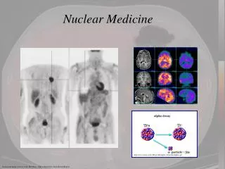
Explore the principles of radionuclides, energy interactions, and gamma camera technology in nuclear medicine instrumentation. Learn about isotopes, half-life, and photon-matter interactions in this comprehensive guide.

E N D
Radionuclides Isotopes Half-life Energy (keV) main decay • 99mTc 6.03 hrs 140 I.T. • 131I 8.05 days 364 • 125I 60.2 days 35 E.C. • 123I 13.0 hrs 160 E.C. • 201Tl 73.0 hrs 135, 167 E.C. • 111In 67.2 hrs 247, 173 E.C. • 67Ga 78.1 hrs 300, 185, 93 E.C. • 127Xe 36.0 days 172, 203, 375 E.C. • 133Xe 5.31 days 81
Photon-Matter Interaction • Photoelectric effect • entire energy converted into kinetic energy • high Z material, Z4E-3 • Compton scattering • part of its energy converted into kinetic energy • proportional to electron density, ZE-1 • predominant interaction in tissue, ( Z )
Attenuation Effect • Ina = I0 exp { -∫d} • : both photoelectric effect & Campton scatter Gamma rays Scattered (Campton) Absorbed (Photoelectric) Non-attenuated
Collimator • Select the direction of photons incident on camera • defining the integration paths • Types: • parallel • slanted parallel • fan-beam • cone-beam • varifocal cone-beam • pinhole • convergent • divergent
Parallel Collimator • Resolution : Rc = S (1+L/H) L, = S/H • Distance dependent (DDSR) • Sensitivity : g Rc2/L2 = 2 (S(S+T))2 • Septa penetration not considered Rc/(H+L) = S/H Rc L L S Septa thickness = T H Rc
Resolution v.s. Distance Collimators • Septal thickness T is determined by photon energy • low-energy collimator < 150 keV • medium-energy collimator < 400 keV High sensitivity resolution General purpose High resolution Rc Source to collimator distance
Scintillator (inorganic) • Convert a gamma-ray photon to light photons for subsequent processing by the PMTs • A large flat NaI (Tl) crystal (eg., 20”x15”) • Issue: sensitivity vs. resolution • Thickness: 1/4” ~ 3/8” • The thicker the crystal, the better the sensitivity but the worse (larger) the resolution. Conduction band Ionization energy Activator excited states Activator ground state Valence band
NaI properties • Stopping power: • Effective atomic number (Iodine:53, relatively high) • Density: 3.76 g/cm3 • Light yield: 38 photons/keV (4 eV/per photon) • Good light yield, used as reference = 100 • Energy resolution (Poisson statics) • no. generated proportional to deposited energy • 15% scintillation Efficiency • Light decay constant: 230s after glow • Dead time • Position mis-positioning • Wavelength at max. emission: 415 nm • Reflective index: 1.85 • Hygroscopic, relatively fragile
Crystal vs. Light yield NaI (Tl) Light yield CsI (Tl) CsI (Na) 420 565 410 Wavelength (nm)
Detector response vs. Energy resolution • Output signal amplitude proportional to energy deposited in the scintillator • Energy resolution = 100% • Complete electron transfer (ideal condition) Non-scatter photon Scatter photon Count Eo/(1+2Eo) Eo Photon energy
Photofraction (real condition) • Spreading due to Poisson effect Non-scatter photon Scatter photon Count FWHM Eo / (1 + 2Eo) Eo Photon energy
Factors affecting Energy resolution: • Counting statistics + Electronic noise • Causes uncertainty in measured deposited energy • Poisson Statistics g(x) = Poisson ((x)) Prob (g(x)) = [(x) g(x)/g(x)!] exp(-(x)) f (n/) = n exp (- )/n! SNR {n/} = E {n/} = Var {n/} = E {g(x)} = (x) Var {g(x)} = (x)
Factors affecting Energy resolution: • 1. Incomplete energy transfer • Detector size • Attenuation effect: density, effective Z number • 2. Pile-ups & Baseline shifts Baseline shift Pile-up
Pile-up and Baseline shift • Problems occurs at high counting rates • Both can be reduced by decreasing the pulse width, but this also increases the electronic noises, thus degrading energy resolution. • Baseline shift: • 2nd pulse occurring during the negative components of the 1st pulse will have depressed amplitude • Shift in the energy of the 2nd event • Corrected by pole zero cancellation or baseline restoration • Pile-up: • Two or more pulses fall on top of each other to became one pulse • Incorrect energy information • Lost events
What is measured ?2D vs3D attenuation distribution radioactivity distribution y –∫ (x, y’)dy’ (x) = ∫{a(x, y, z) * h (x, y, z) } e dy + s (x , z) = Ε { (x , z) } DDSR attenuation factor scatter 期望值 y x Gamma Camera
Light guide Scintillator Light Guide Light photon PMT photocathod
PMTs • Convert a light photon to electrical charges light guide scintillator dynodes anode e– Output signal 106 e–’s photocathode light photon 10 ~ 12 dynodes 一般約 30% photons 可經 light guide 到 PMTs
Pulse Processing: Pre-Amplifying • Preamplifier (preamp): • To match impedance levels to subsequent components • To shape the signal pulse (integration) • RC = 20~200μs • To (sometimes) amplify small PMT outputs • Should be located as close as possible to the PMT PMT C R 50μs Preamplifier 250 ns 500μs
Pulse Processing: Amplifier • Amplifier • To amplify the still relatively small signal • Perform pulse shaping • Convert the slow decaying pulse to a narrow one • To avoid pulse pile-ups at high counting rates PreAmp Amplifier
Positioning logic (Anger) Y+ …… X+ X+ X- X- Y+ Y- Position determination PMT array X = X+ + X- Y = Y+ + Y- Z = X+ + X- + Y+ + Y- Y-
Anger Positioning logic Position determination X k (X++X-)/Z Y k (Y++Y-)/Z A PHA (pulse height analyzer) is to select for counting only those pulses falling within selected amplitude intervals or “channels” A SCA (single channel analyzer) is a PHA having only one channel: NaI (Tl) Detectors Positioning logic circuit SCA Z X Y ULD: upper level discriminator LLD: lower level discriminator PHA Gating signal A/D
Analog System X/Z X SUM Collimator Crystal Y/Z Y SUM Z energy SUM Anger Registor matrix Summed analog outputs PMT array PreAMPs
Digital System ADCPMT ADC PMT BUS SUM ADC SUM ADC SUM ADC SUM Programmable Digital Event Processor Collimator ADC Crystal SUM ADC SUM ADC SUM ADC SUM ADC SUM Individual PMT data to digital event processor ADC SUM PMT array Analog to Digital Converters PreAMPs
PSPMT • position sensitive PMT • essentially light guide is not necessary • perform multi-positioning within one PMT X X Y Y Z
SPECT scanner • Multi-head systems: • 1. Provide higher sensitivity • 2. Allow simultaneous emission and transmission scans • 3. More expensive
Performance Characteristics: • Image Non-linearity • straight lines are curved • X and Y signals do not change linearly with the distance of the detected events • variations in PMT collection efficiency acrossing its aperture • variations in PMT sensitivity • non-uniformities in optical coupling, etc. • Image Non-uniformity • flood field-image shows variations in brightness • non-uniform detection efficiency and nonlinearities • differences in pulse-height spectrum of the PMTs
Performance Characteristics: Spatial Resolution • overall resolution R2 = Ri2 + Rc2 • affecting image contrast and visualization of small structures • introduce bias • intrinsic resolution Ri • crystal thickness (light distribution) • crystal density, effective Z number (multiple scattering) • light yield (statistical variations in pulse heights) • degraded with decreasing g-ray energy (light yield) • improves with increased light collection and detection efficiency • improves with image uniformity and digital positioning • expected resolution limit for NaI (Tl) = 2mm • collimator resolution Rc • collimator design • source to collimator distance
Performance Characteristics: cont’d • Detection Efficiency: • Crystal thickness, density, effective Z number • almost 100% at up to 100 keV, but drops rapidly with increasing energy to about 10~20% at 500 keV • Collimator efficiency • affecting image noise • introduce variance while quantitative studying • 100 ~ 200 keV is the best optimal energy of Anger camera (g-ray) • at low energy, deteriorating spatial resolution • at high energy, deteriorating detection efficiency
Performance Characteristics: baseline shift Count rate: • Mis-positioning • baseline shift • pile-up • simultaneous detection of multiple events at different locations • dead time • 0.5~5s • behaves as nonparazable model: 2nd event ignored if it occurs during the deadtime of the preceding events pile-up nonparalyzable ideal Observed count rate, Ro paralyzable real True count rate, Rt
SPECT reconstruction: • Issues: attenuation, scatter, noise, DDSR, sampling geometry • Filtered Backprojection (FBP) • ignore attenuation, DDSR • usually no scatter correction • ad hoc smoothing for controlling image noise • Iterative Reconstruction • OSEM • allow attenuation, and DDSR corrections • optimal noise control • usually no scatter correction • needs attenuation map • Analytical approaches uniform attenuation • Simultaneous Emission, Attenuation map Reconstruction • Dynamic SPECT by interpolation vs. timing
Newer developments: • Coincidence Imaging (PET like) • Low cost • Poor sensitivity and resolution • g ray septa penetration • Simultaneous Transmission and Emission Imaging • Registered attenuation map • Spill-down scatters from the transmission source • Truncation error remains unsettled …………………….. • Dual Isotope Imaging • Increase diagnosis specificity • Issues: spill-down scatters from high to low energy window
Newer developments: cont’d • Small-animal gamma camera • Small FOV, higher resolution • Depth-of-interaction (DOI) detectors • Better spatial resolution • Allow use of thicker NaI crystal • Semi-conduction imager • Converts g ray directly into electrical signals • Promising candidate: CdZnTe detector • Novel designs • Scintimammography • Placed closer to the source by odd geometry • Optimizing resolution & sensitivity M T P exit window fiber NaI (Tl) entrance window reflectors detector Indium hump bonds readout IC
Newer developments: cont’d • Novel designs • CERESPECT • A single fixed annular NaI (Tl) crystal completely surrounding the patient’s head • A rotating segmented annular collimator • Modular systems: • SPRINT II brain SPECT • 11 modules in a circular ring around the patient’s head, each module consists of 44 one-dimensional bar NaI (Tl) scintillation camera • Rotating split or focused collimators • FASTSPECT • A hemispherical array of 24 modules for brain imaging • Each module views the entire brain through one or more pinholes • Stationary system, easy dynamic imaging