Download
1 / 21
210 likes | 352 Views
The MGPA ECAL readout chip for CMS. Multi–Gain Pre-Amplifier - 0.25 m m CMOS chip for CMS ECAL. OUTLINE Introduction Design Measured Performance Conclusions. Mark Raymond , Geoff Hall, Imperial College London, UK.

E N D
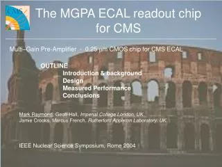
The MGPA ECAL readout chipfor CMS Multi–Gain Pre-Amplifier - 0.25 mm CMOS chip for CMS ECAL OUTLINE Introduction Design Measured Performance Conclusions Mark Raymond, Geoff Hall, Imperial College London, UK. Jamie Crooks, Marcus French, Rutherford Appleton Laboratory, UK. 9th Workshop on Electronics for LHC Experiments, Amsterdam, 2003 LHC Electronics Workshop, Amsterdam, 2003
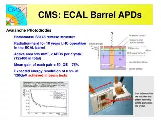
New CMS VFE (Very Front End) architecture CMS ECAL Lead Tungstate crystal calorimeter with APD/VPT readout for barrel/endcap General approach use multiple gain ranges -> high resolution with only 12 bit ADC only transmit value for highest gain channel-in-range => have to take decision on front end Previous architecture range decision taken in preamplifier (complex chip), followed by single channel commercial ADC New architecture 3 parallel gain channels (MGPA), multi-channel ADC, range decision taken by logic in ADC chip use 0.25 mm CMOS to take advantage of: radiation hardness system simplifications: single 2.5V supply, power savings short production turnaround, high yield, cheaper Short timescale for development design begun mid 2002, submission early 2003, die received May 2003, packaged die since August 12 LOGIC 12 bits 6 2 bits 1 opto-electric barrel: APD endcap: VPT MGPA Multi-channel ADC LHC Electronics Workshop, Amsterdam, 2003
MGPA Target Specifications Barrel/Endcap read out using APD/VPT different capacitance and photoelectric conversion factors spec. review -> 3 gain ranges sufficient to deliver required performance -> MGPA design easier Additional calibrate feature -> not precision but allows charge injection to each front end chip Vpk-25 Vpk LHC Electronics Workshop, Amsterdam, 2003
MGPA Architecture 1st stage RFCF = 40 nsec. (avoids pile-up) choose RFCF for barrel/endcap external components => 1 chip suits both 3 gain channels 1:6:12 set by resistors (on-chip) for linearity differential current O/P stages external termination 2RICI = 40 nsec. => low pass filtering on all noise sources within chip calibration facility prog. amplitude needs ext. trigger I2C interface to programme: output pedestal levels enable calibration feature cal DAC setting i I2C and offset generator RI CI i VCM RG1 RI i DAC RI CI VCM RG2 RI ext. trig. CCAL charge amp. RI CI VCM RG3 I/P RI diff. O/P stages gain stages RF CF RFCF LHC Electronics Workshop, Amsterdam, 2003
Noise Sources Rpf diff. O/P gain stage transconductance gain stage vRpf2 CI Cpf iCGFET2 s.f. RG RI vFET2 CIN charge amp. iRG2 VCM 1st stage Rpf dominates: 4900 electrons (barrel: Cpf//Rpf = 33 pF//1k2), 2700 (endcap: Cpf//Rpf = 8p2//4k7) I/P FET: W/L = 30,000/0.36, gm ~ 0.3 A/V -> 1800 electrons (barrel, 200pF), 660 (endcap, 50pF) => no strong dependence of overall noise on CIN gain stages high and mid gain ranges, RG low (few 10’s W) additional noise small low gain range, RG (240 W) and CG FET noise dominate and spec. exceeded (factor ~3) but lowest gain range used for biggest signals => electronic noise contribution to overall energy resolution very small (for this range) LHC Electronics Workshop, Amsterdam, 2003
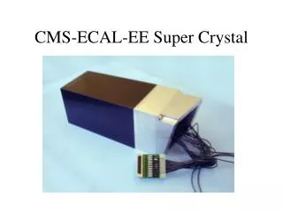
Chip Layout layout issues gain channels segregated as much as poss. with separate power pads -> try to avoid inter-channel coupling lots of multiple power pads die size ~ 4mm x 4mm packaged in 100 pin TQFP (14mm x 14mm) offset gen. I2C diff. O/P stage high gain stage diff. O/P stage mid gain stage 1st stage low gain stage diff. O/P stage LHC Electronics Workshop, Amsterdam, 2003
Test Setup early tests used bare die – packaged chips only available more recently priority given to measurements for barrel gain (60 pC fullscale) True rms milli-voltmeter Pulse Gen. Programmable Attenuator Scope diff. probe MGPA test board LHC Electronics Workshop, Amsterdam, 2003
Pulse Shape Measurements low gain range mid gain range high gain range O/P signals probed individually 0 – 60 pC, 40 steps saturation in mid and high gain ranges no clamping outside linear range Volts time [nsec] LHC Electronics Workshop, Amsterdam, 2003
Differential Pulse Shape Measurements low gain range mid gain range high gain range differential O/P signals (diff. probe) 0 – 60 pC, 40 steps no obvious signs of distortion in lower gain ranges => effective gain channel segregation in layout gain ratios 1 : 5.6 : 11.3 (c.f. 1 : 6 : 12) Volts linear range time [nsec] LHC Electronics Workshop, Amsterdam, 2003
Linearity: High Gain Channel linearity within (or close to) spec for a range of gain stage bias currents => not v. sensitive to bias conditions linearity [% fullscale] spec. relative signal size 5.4 pC Linearity [% fullscale] = peak pulse ht. – fit (to pk pulse ht) X100 fullscale signal LHC Electronics Workshop, Amsterdam, 2003
Linearity: Mid and Low gain channels mid low spec. linearity [% fullscale] relative signal size 11 pC 60 pC similar picture to high gain channel LHC Electronics Workshop, Amsterdam, 2003
Pulse Shape Matching Vpk Vpk-25 pulse shapes for all 3 gain ranges (11 steps / range) all 33 pulse shapes overlaid normalise to max pulse ht. pulse height [Volts] time [nsec.] pulse shape matching important within and across gain ranges to quantify use pulse shape matching factor, PSMF = Vpk-25 Vpk LHC Electronics Workshop, Amsterdam, 2003
Pulse Shape Matching pulse shape matching close to spec. (+/- 1%) spec. pulse shape matching [%] relative signal size [1=fullscale] Pulse shape matching [%] = (PSMF – Average PSMF) x 100 Average PSMF (Average PSMF = average over all pulse shapes and all 3 gain ranges) LHC Electronics Workshop, Amsterdam, 2003
Noise use wide bandwidth true rms meter (single ended I/P) => need diff. to singled ended buffer circuitry (adds some extra filtering) => extra buffer noise contribution to subtract within spec. < 10,000 (barrel) < 3,500 (endcap) electronic noise not significant for low gain range weak dependence on input capacitance as expected estimated errors: ~ 10% high and mid-gain ranges, ~ 20% low gain range (buffer circuitry dominates here) LHC Electronics Workshop, Amsterdam, 2003
Radiation Tests low mid high pre-rad 5 Mrads 10 keV X-rays (spectrum peak) , dosimetry accurate to ~ 10%, doserate ~ 1 Mrad/hour, no anneal ~ 3% reduction in gain after 5 Mrads (2 x worst case) no measurable effect on noise LHC Electronics Workshop, Amsterdam, 2003
I2C Pedestal Adjust I2C=0 I2C=50 I2C=100 ADC I/P range Volts VCM nsec. High gain range, ~ fullscale signal. I2C pedestal adjust sets offset current to diff O/P stage (one for each gain range) I2C ~ 50 about right in this case LHC Electronics Workshop, Amsterdam, 2003
On-chip Calibration external edge trigger Volts ext. 10pF MGPA I/P I2C simple DAC allows programmable (I2C) amplitude charge injection -> range of signal sizes for each gain range external trigger required allows functional verification during chip screening and in-system nsec. LHC Electronics Workshop, Amsterdam, 2003
Power, Yield, Things to fix Power consumption bias currents to all stages set by external resistors 240 mA drawn from 2.5 V rail => 600 mW (1st stage: 150, gain stages: 300, diff. stages: 150) Yield appears very high, e.g. only one faulty chip found in basic tests on ~ 50 chips Things to fix/change high frequency instability around first stage ext. feedback components + packaging/PCB layout capacitance + bond inductance -> LC resonance can be made stable insert small series damping resistors and reduce bandwidth better fix? – needs more study add on-chip reference for offset bias generator modify default I2C settings Vs I/P LHC Electronics Workshop, Amsterdam, 2003
Conclusions First iteration of MGPA successful Analogue performance good gain linearity pulse shape matching noise rad-hard as expected What next? Verify performance can be maintained in system in conjunction with APD (& VPT), ADC, rest of FE components - work already underway at CERN timescale short - next submission (engineering run) soon within (or v. close to) spec. LHC Electronics Workshop, Amsterdam, 2003