Download
1 / 26
260 likes | 391 Views
RPS GROUP OF INSTUTIONS. SATNALI ROAD, BALANA(MOHINDERGARH) -123029. SUMMER TRAINING REPORT ON ‘ EMBEDDED SYSTEM ’ BY SOFCON. Submitted to : Submitted by :

E N D
RPS GROUP OF INSTUTIONS SATNALI ROAD, BALANA(MOHINDERGARH) -123029 SUMMER TRAINING REPORT ON ‘ EMBEDDED SYSTEM’ BY SOFCON Submitted to : Submitted by : Mr. KARAMBIR SHEORAN SANDEEP Asstt. Professor & Head 1130112367 ECE Deptt. Department of Electronics & Communication Engineering
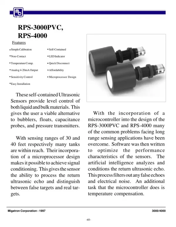
Embedded Systems • Embedded system means the processor is embedded into that application • An embedded product uses a microprocessor or microcontroller to do task • In an embedded system, there is only one application software that is typically burned into ROM • Example printer, keyboard, video game player
Microcontroler • Features of 8051 • ROM - 4K bytes • RAM - 128 bytes • Timer - 2 • I/O pins - 32 • Serial port - 1 • Interrupt sources - 6 • 8051 is based on CISC architecture. • It is based on Harvard architecture. So, it has separate program and data memory.
Block Diagram of 8051 External interrupts Counter Inputs On-chip ROM for program code Timer/Counter Interrupt Control Timer 1 On-chip RAM Timer 0 CPU Serial Port Bus Control 4 I/O Ports OSC P0 P1 P2 P3 TxD RxD Address/Data
What is a microprocessor? • The microprocessor is the integration of a number of useful functions. These functions are: • The ability to execute a stored set of instructions to carry out user defined tasks. • General-purpose microprocessor. • Act as CPU for Computers. • No RAM, ROM, I/O on CPU chip itself • Example Intel’s 8086 ,8085.
Microprocessor v/s Micro-controllers • Microprocessors • High end of market where performance matters • High power dissipation–high cost • Need peripheral devices to work • Mostly used in microcomputers • Microcontrollers • Targeted for low end of market where performance doesn’t matter • Low power dissipation – low cost • Memory plus I/O devices, all integrated into one chip • Mostly used in embedded systems
Introduction to C programming Powerful features, simple syntax, and portability make C a preferred language among programmers for business and industrial applications. Portability means that C programs written for a computer with a particular kind of processor, say Intel, can be executed on computers with different processors such as Motorola, Sun Sparc, or IBM with little or no modification Origin of C Dennis M. Ritchie, a systems engineer at Bell Laboratories, New Jersey developed C in the early 1970’s. Where is C useful? The following is a partial list of areas where C language is used: Ø Embedded Systems Ø Systems Programming Ø Artificial Intelligence Ø Industrial Automation Ø Computer Graphics Ø Space Research Ø Image Processing Ø Game Programming Use of c
LED [LIGHT EMITTING DIOIDE] A light-emitting diode (LED) is a semiconductor light source. LEDs are used as indicator lamps in many devices
STRUCTURE OF LED Like a normal diode, the LED consists of a chip of semiconducting material doped with impurities to create a p-n junction. As in other diodes, current flows easily from the p-side, or anode, to the n-side, or cathode.
LEDs are produced in a variety of shapes and sizes. The 5 mm cylindrical package (red, fifth from the left) is the most common, estimated at 80% of world production.The color of the plastic lens is often the same as the actual color of light emitted, but not always. For instance, purple plastic is often used for infrared LEDs, and most blue devices have clear housings. There are also LEDs in SMT packages, such as those found on blinkies and on cell phone keypads (not shown). The main types of LEDs are miniature, high power devices and custom designs such as alphanumeric or multi-color Types
CODING FOR LED BLINKING #include<reg51.h> #define led P1 void msdelay(unsigned int); void main() { while(1) { led=0xff; msdelay(44); led=0x00; msdelay(44); } } void msdelay(unsigned int t) { unsigned inti,j; for(i=0;i<=1233;i++) for(j=0;j<=t;j++); }
7-segment LED Display is display device which can display one digit at a time • Actually one digit is represented by arrangement of 7 LEDs in a small cubical box • For representing 3 digit number we need three 7-segment LED Displays • 7-segment LED Display look like
case 1: seg=0x06; break; case 2: seg=0x5b; break; case 3: seg=0x4f; break; case 4: seg=0x66; break; case 5: seg=0x6d; break; case 6: seg=0x7d; break; case 7: seg=0x07; break; case 8: seg=0x7f; break; case 9: seg=0x67; break; }}} #include<reg51.h> #define seg P1 sbit inc=P2^0; sbitdec=P2^1; void main() { unsigned int k=0,i; while(1) { if(inc==0) { k=k+1; for(i=0;i<=35000;i++); } if(dec==0) { k=k-1; for(i=0;i<=35000;i++); } switch(k) { case 0: seg=0x3f; break; CODING FOR 7 SEG LED
PROTEUS DESIGN 7 SEG LED CKT DIAGRAM
RS – register select If RS=0, used to send commands such as clear display, cursor position etc. If RS=1, used to send data to the LCD. R/W – read / write If R/W = 1, read from LCD If R/W = 0, write to LCD E – enable A 450 nano seconds high-to-low pulse is applied in order to send data. LCD Address DESCRIPTION For 16x2 LCD the address of the cursor positions are: All these addresses are in hexadecimal.
Addressing Modes • The CPU can access data in various ways. The data could be in a register or in memory or be provided as an immediate value. These various ways of accessing data are called addressing modes. • Total 5 addressing modes: • 1) Immediate • 2) Register • 3) Direct • 4) Register indirect • 5) Indexed
Immediate addressing mode • Ex: • MVI A,25H;load 25h into A • Immediate data must be preceded by the pound sign “#”. • Although DPTR is 16 bit, it can be accessed as two 8-bit registers, DPH and DPL. • Ex: • MOV DPTR, #2550h • is same as, • MOV DPL, #50h • MOV DPH,#25h
Register Addressing Modes • Ex: • MOV A, R0 ;copy contents of R0 into A • Direct addressing Mode • Ex: • MOV R0,40h ;save the contents of RAM location 40h in R0 • MOV 56h,A ;save the contents of A in RAM location 56h • The‘#’ symbol distinguishes between the direct addressing and immediate addressing mode.
Register Indirect addressing Mode • Here register is used as a pointer to the data. • If the data is inside CPU, only registers R0 and R1 are used for this purpose. • When R0 and R1 are used as pointers, i.e., when they hold the address of RAM, they must be preceded by “@” sign. • Ex: • MOV A,M; • MOV @R1,B;move contents of B into RAM location whose address is held by R1.