Download
1 / 1
10 likes | 173 Views
Separation of Scintillation and Cerenkov Light in an Optical Calorimeter Heejong Kim on behalf of DREAM collaboration Dept. of Physics, Texas Tech University. 1. Introduction. 3. Results. Dual-Readout Module(DREAM) calorimeter showed that

E N D
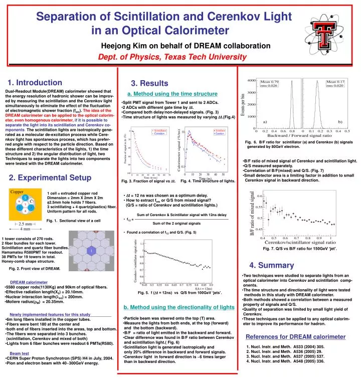
Separation of Scintillation and Cerenkov Light in an Optical Calorimeter Heejong Kim on behalf of DREAM collaboration Dept. of Physics, Texas Tech University 1. Introduction 3. Results Dual-Readout Module(DREAM) calorimeter showed that the energy resolution of hadronic shower can be improv- ed by measuring the scintillation and the Cerenkov light simultaneously to eliminate the effect of the fluctuation of electromagnetic shower fraction (fem). The idea of the DREAM calorimeter can be applied to the optical calorim- eter, even homogenous calorimeter,if it is possible to separate the light into its scintillation and Cerenkov co- mponents. The scintillation lights are isotropically gene- rated as a molecular de-excitation process while Cere- nkov light has spontaneous process, which has prefer- red angle with respect to the particle direction. Based on these different characteristics of the lights, 1) the time structure and 2) the angular distribution of light, two Techniques to separate the lights into two components were tested with the DREAM calorimeter. a. Method using the time structure • Split PMT signal from Tower 1 and sent to 2 ADCs. • 2 ADCs with different gate time by Dt. • Compared both delay/non-delayed signals. (Fig. 3) • Time structure of lights was measured by varying Dt.(Fig.4) Fig. 6. B/F ratio for scintillator (a) and Cerenkov (b) signals generated by 80GeV electron. • B/F ratio of mixed signal of Cerenkov and scintillation light. • Q/S measured separately. • Correlation of B/F(mixed) and Q/S. (Fig. 7) • Small detector area is a limiting factor in addition to small • Cerenkov signal in backward direction. 2. Experimental Setup Fig. 3. Fraction of signal vs Dt. Fig. 4. Time structure of lights. 1 cell = extruded copper rod Dimension = 2mm X 2mm X 2m f2.5mm hole holds 7 fibers. 3 scintillating + 4 quartz(plastics) fiber. Uniform pattern for all rods. • Dt = 12 ns was chosen as a optimum delay. • How to extract fem or Q/S from mixed signal? • (Q/S = ratio of Cerenkov and scintillation lights.) • Sum of Cerenkov & Scintillator signal with 12ns delay • f12 = • Sum of the 2 original signals • Found a correlation of f12 and Q/S. (Fig. 5) Fig. 1. Sectional view of a cell 1 tower consists of 270 rods. 2 fiber bundles for each tower. Scintillation and quartz fiber bundles. Hamamatsu R580PMT for readout. 38 PMTs for 19 towers in total. Honey-comb shape structure. Fig. 7. Q/S vs B/F ratio for 150GeV ‘jet’. 4. Summary Fig. 2. Front view of DREAM. • Two techniques were studied to separate lights from an • optical calorimeter into Cerenkov and scintillation comp- • onents. • The time structure and directionality of light were tested • methods in this study with DREAM calorimeter. • Both methods showed a correlation between a measured • property of signals and Q/S. • Quality of separation was limited by small light yield of • Cerenkov. • These techniques can be applied to any optical calorim- • eter to improve its performance for hadron. • DREAM calorimeter • 5580 copper rods(1130Kg) and 90km of optical fibers. • Effective radiation length(X0) = 20.10mm. • Nuclear interaction length(lint) = 200mm. • Moliere radius(rM) = 20.35mm. Fig. 5. f (Dt = 12ns) vs Q/S from 100GeV ‘jets’. b. Method using the directionality of lights • Newly implemented features for this study • 6m long fibers installed in the copper tubes. • Fibers were bent 180 at the center and • both end of fibers inserted into the areas, top and bottom. • The fibers were separated into 3 bunches. • (scintillation, Cerenkov and mixed of both) • Lights from 6 fiber bunches were readout 6 PMTs(R580). • Particle beam was steered onto the top (T) area. • Measure the lights from both ends, at the top (forward) • and the bottom (backward). • B/F = ratio of light emitted in the backward and forward. • Clear difference was found in B/F ratio between Cerenkov • and scintillation light.( Fig. 6) • Scintillation light is generated isotropically and • only 20% difference in backward and forward signals. • Cerenkov light in forward direction is ~6 times larger • than in backward direction. References for DREAM calorimeter 1. Nucl. Instr. and Meth. A533 (2004) 305. 2. Nucl. Instr. and Meth. A536 (2005) 29. 3. Nucl. Instr. and Meth. A537 (2005) 537. 4. Nucl. Instr. and Meth. A548 (2005) 336. • Beam test • CERN Super Proton Synchrotron (SPS) H4 in July, 2004. • Pion and electron beam with 40~300GeV energy.