Download
1 / 40
410 likes | 612 Views
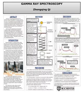
Development of high-pressure Xe ionization chambers for gamma-ray spectroscopy Aleksey Bolotnikov Brookhaven National Laboratory Workshop on Xenon-Based Detectors, Berkeley November 16-18 2009. Introduction Electron transport and spectroscopic properties of HPXe

E N D
Development of high-pressure Xe ionization chambers for gamma-ray spectroscopy Aleksey Bolotnikov Brookhaven National Laboratory Workshop on Xenon-Based Detectors, Berkeley November 16-18 2009
Introduction Electron transport and spectroscopic properties of HPXe HPXe detector technology (purification, gas filling) Detectors designs and applications Conclusion Outline
HPXe is attractive medium for room-temperature gamma-ray detectors Advantages of Xe stable, uniform withstand high radiation and high temperature environments compressed Xe has high stopping power (Z=54, r=0.5 g/cc) small Fano-factor, ~0.13 compare 0.06-0.13 for Ge low cost => large volume Several competing detectors suitable for room-temperature operation: NaI(Tl), CdZnTe, LaBr3 pushing Xe behind in the areas where the small and compact devices are required But there are several niches remaining for Xe detectors, e.g., portal and environmental monitors, measurements is harsh environments (high temperature, high radiation) Advantages of high-pressure Xe as detector medium
Despite the small Fano-factor predicted for LXe, its energy resolution is ~6% at 662 keV. This was explained by fluctuations of the recombination rate caused by d-electrons in dense Xe (B. Rodionov) The statistical limit, ~0.6% at 662 keV, was achieved at low densities Compressed Xe was proposed as alternative to LXe. It would provide high stopping power while retain good resolution of low pressure gas However, in reality the intrinsic resolution starts degrades at much low densities that expected Combination of two effects can explain this dependence: fluctuation of recombination (d-electron model) plus formation of large Xe cluster with liquid-like properties above 0.5 g/cc Intrinsic energy resolution of HPXe Energy resolution at 662 keV vs. Xe density Threshold Measurements were taken at high electric field 5-7 KV/cm Limit on max operation density: < 0.55 g/cm3
Xe+ 3He mixture irradiated with thermal neutrons In the past, several experiments indicated clusters formation and its step-like density dependence: photoluminescence and photocondactivity measurements. 3He+n -> triton (191 keV ) + proton (573 keV) (neglecting the kinetic energy of the thermal neutron). Tritons and protons have very small ranges in high-density xenon. Assuming a uniform density of xenon gas at a density of 0.2 g/cm3, proton and triton ranges are less then 200 m. Spectra generated by thermal neutrons in Xe+3He mixture A. Bolozdynya, A. Bolotnikov, J. Richards, A. Proctor, NIM A522, 595-597, 2004.
Intrinsic resolution measured at different energies 1275 keV 835 keV Intrinsic resolution, % 392 keV 166 keV 122 keV Xe density, g/cc Romanuk, Dmitrinko, MEPHI
To overcame electron-ion recombination and achieve intrinsic-level resolution the electric field strength in the drift region should be > 2 KV/cm 2% is comparable with the resolutions of typical CZT and LaBr3 detectors and much better than those obtained for large volume NaI detectors High electric field is required to achieve intrinsic energy resolution in compresses Xe Energy resolution vs. electric field strength
If clusters formation can be suppressed by heating the gas this may improve energy resolution at densities > 0.6 g/cc? Temperature effect on energy resolution Relative changes of the total collected charge and energy resolution measured at 5 KV/cm for two densities; 0.5 and 0.7 g/cc (662 keV) Deteriorate No effect 0.7 g/cc 0.5 g/cc Later, Dmitrenko et al. proved that energy resolution in HPXe (~0.5 g/cc) does not changed up to 200 C. => HPXe can be used at high-temperatures where other techniques do ton work, e.g., responses of semiconductor detectors rapidly degrade with temperature.
W-value at low pressure is ~21 eV The W-value decreases with Xe density approximately as linear function to ~15.6 eV measured at LXe At low densities such decrease is attributed: Xe+Xe+hvXe2* Xe2* Xe2++e— At high densities, W decreases because of the formation of the electronic band structure Changes of the W-value in compressed Xe Relative changes of the W-value vs. density Bolotnikov, Ramsey (1995 ) W is ~20 eV at 0.6 g/cc => low amplitude signals in comparison to CZT (~5 eV). Electronic and other noises are more critical in HPXe.
Low mobility in pure Xe, drift velocity saturates at ~1 mm/ms, 5 cm - 50 ms The electron transport crossection has a deep minimum around 0.3-1.0 eV (Ramsauer–Townsend effect) Several admixtures, e.g., H2, N2, CH4 and other organics, increase the mobility H2 and N2 are the most practical because they can withstand the spark purification High concentration of H2 requires stronger electric field! The optimal concentration of H2 is 0.2-0.3% at the electric field of > 2 KV/cm. The velocity increases 2-5 times Slow detector in comparison to CZT 1.0% 0.7% 0.5% 0.3% 0.2% Pure Xe Electron drift velocity Electron drift velocity vs. electric field strength in Xe+%H2 mixture at 0.6 g/cm3 Dmitrenko, Romanuk (1980)
Comparison of stopping power of • several detector materials at 662 keV • 10-cm layer of Xe at 0.5 g/cc is equivalent to • ~0.5 cm of HgI2 • ~1 cm of CZT • ~1 cm LaBr3 • ~1.5 cm of NaI(Tl) • ~2 cm of Ge • The low stopping power can be compensated by the large area and volume, e.g., one 10-liter cylindrical ionization chamber (10 cm diameter and 100 cm long) has ~1000 cm2 area which is equivalent to ~ 500 1 cm3 CZT ( $20 K vs. $500 K) ! • 10-liter HPXe detector is equivalent to a standard 6” NaI(Tl) detector Stopping power of HPXe HPXe detectors provide large effective areas and can replace NaI, CZT and Ge detectors in the areas where large effective area detectors are required.
Performance characteristics: Energy resolution is 2.0-2.5% at 662 keV and < 1.5% at > 1 MeV Temperature range 15-200 C Large volume, large effective area Relatively low-cost, long-term stability Large-volume, up to 1000 cm3, high-sensitive spectrometers (single or arrays) for portal applications and environmental monitoring (remotely, without servicing) Small, < 200 cm3, rugged devices for application in harsh environments (high-radiation, high-temperature, high-vibrations, etc.), e.g., active zone of nuclear reactors, radioactive waste, well-logging. Expected performance and application arias Portal security and environmental monitoring Nuclear Well Logging
Challenges: Purification and handling of Xe, electron lifetime, > 1 ms Design constraints associated with high-pressure, ~50 atm, high-voltage, 20-30 KV, low-outgas materials (high-density ceramic, SS, Al, Ti) Relatively weak output signals: the W-value in HPXe is ~20 eV ( ~5 eV in CZT) High-sensitivity to acoustic noise due to high capacitance of bulky electrodes proportional mode is not possible at high-pressure, > 20 atm ionization mode: both charge and scintillation light can be used to generate output signals primary scintillation light signal is weak, but still can be used as a trigger practically it is difficult to detect light signals in high-pressure chambers II. HPXe technology
Xe purification and filling system at BNL • Two stages of purification: • preliminary purification with high-temperature getters for Xe and H2 • spark-discharge for fine purification • The system ensures high purity of Xe during and after the filling
High-pressure cylinder with spark-discharge purifier containing 1000 l of ultra-pure Xe There are several tricks how to prepare and fill detectors Practically, we never used getters to purify Xe; we keep them just in case Spark purifier is the most efficient technique: e.g., it took ~2 hr to purify ~1000 l of Xe, purchased from Spectra Gases, Inc, to a purity level of > 2 ms measured at room temperature at ~60 atm Xe purification and filling system at BNL
Spark-discharge produces microscopic Ti dust that trap with high efficiency electronegative molecules such as O2, CO, CO2, H2O, organics Require ~10 KV bias and ~2 mA Small amount of Ti dust can be introduced inside a detector during the filling to ensures that Xe gas stays pure inside a detector for very long time, year Spark purifier and purity monitor Spark Discharge region Ionization chamber for monitoring Xe purity
A small ionization chamber placed inside the spark purifier detects the muon tracks (one event per 20-30 sec) Simple and robust Allows to measure purity inside the spark purified and inside the detector Monitoring the electron lifetime by measuring their drift time Purity monitor Drift time measurements t The drift time gives a low estimate for the lifetime Do not try to detect vertical events in HP!
Measurement of Xe density • The dielectric constant e is related to a density • The ratio R0=(e-1)/(e+2)is approximately a linear function of density: R0 =Ar+Br2,A=10.9 cm3/mole • The dielectric constant e can be measured as a capacitance between two adjacent electrodes inside the chamber: e=C/C0 • During the measurements, a test pulse generator in connected to one electrode while the amplitude of the induced signals is used to estimate the capacitance • Accuracy is < 5% A. Bolotnikov and B. Ramsey, NIMA, 383 (1996) 619
Two geometries have been used for HPXe ionization chambers: parallel plate and cylindrical Parallel plate geometry is not suitable for large volume detectors operating at high pressure detectors have large “dead” regions that result in a significant background caused Compton scattering Cylindrical geometry: optimal for high-pressure vessels with thin walls: ~2 mm of SS or ~5 mm of Al (for 12-cm diameter vessel) HV can be directly applied to the vessel walls used as a cathode allows for making large-volume, > 10 l, detectors by using long cylindrical vessels III. Designs of HPXe ionization chambers
The drift region was limited by max bias that can be applied, 25 KV, and field ratio Energy resolution is mainly determined by shielding inefficiency of the Frisch-grid Xe density 0.5 g/cc Sensitive volume 0.5 liter Energy resolution better than 2% Ti vessel, no hydrogen added HPXe chamber built at BNL G. Smith, P. Vanier, and G. Mahler, BNL
A portable spectrometer based on BNL’s chamber Large Compton continuum is due a significant fraction of dead regions inside the chamber This chamber set a new record of stable operation time, >12 years System built by G. Smith and P. Vanier
Symmetrical design have several benefits: slotted anode to reduce the shielding inefficiency provides more rigid design Xe density 0.5 g/cc Sensitive volume 1 liter Energy resolution better than 2.5% Uses Al vessel because Ti corrosion in a presence of H2 HPXe chamber designed by MEPhI, Russia Symmetrical two-drift region chamber • This gamma-ray spectrometerwas a part of gamma-ray burst searching instrument onboard MIR space station • Continuously operated for > 10 years
Cylindrical geometry improves performance of Xe ionization chambers: shielding inefficiency can be reduced to ~1% since the field lines concentrate toward the anode, a smaller field ratio is required to get 100% electron transmission => less HV is required (this very important improvements) The very first attempts to build cylindrical ionization chambers were not successful because they had the Frisch-grids made of stretched wires: very fragile, highly sensitive to acoustic noise. They did not show good performance. Cylindrical ionization chamber with Frisch-grid Schematic of cylindrical ionization chamber Electric field line distribution near the anode
Cylindrical ionization chamber with a self-supporting Frisch-grid made of a mesh Significant improvements in mechanical stability and performance of cylindrical ionizations chambers were achieved by using SS or Ni electroformed meshes Several chambers were developed by group from MFSC/NASA: 5 cm diameter, 20 cm long Density 0.35 g/cc HPXe 2% Spectroscopic performance similar to CZT detectors and much better than NaI (Tl). This chamber became a baseline prototype for many other designs HPXe Best CZT 6x6x15 mm3 Bolotnikov, Ramsey, TNS IEEE, 1998
Design of a commercial cylindrical ionization chamber with the self-supporting Frisch-grid HV feedthroughs Supporting insulators Anode Grid Typical design adopted by vendors (CTC in cooperation with MEPhI) HV feedthrough adopted from MSFC (bulky, low-cost, for prototyping) Ceramic spokes supporting a grid Dimensions: Length is up to 100 cm Diameter is up to 12 cm Xe pressure ~0.4-0.5 g/cm3 (depending on the chamber’s diameter)
Commercial ionization chamber designed by MEPhI 1. PMT 2. Cylindrical ionizationchamber 3. Frisch grid 4. Anticoincidence scintillator 5. Electronics 6. Charge sensitive amplifier 7. High voltage supply 8. Ceramic feed-through 9. Hermetical vessel 10. Anode • Uses specially designed HV feedthroughs to support the Frisch-grid and the anode • Three modifications of ionization chambers were developed based on this design: 0.2, 2.0, and 10 liters
Commercial ionization chambers developed at MEPhI 2-liter chamber Energy range (50-5000) keV FWHM at 662 keV 2% keV Density of Xe 0.4-0.5 g/cm³ Diameter 120 mm Length 300 mm Total mass 6 kg Voltage ± 24 V Power 10 W The chamber is sealed inside a plastic can to avoid the effect of moisture 0.2-liter chamber
Large volume Xe detectors resolves low- and high energy gamma-ray lines Energy spectra measured with ionization chambers developed by MEPhI V. Dmitrenko et al, MEPhI Eu-152 Th-232
Effect of radiation on detectors responses measured by MEPhI group HPXe detectors have low activation by neutrons Spectra from High Pressure Xenon Detector (120 mm, L=500 mm, M= 1.8kg) before and after activation by Pu-Be neutron source (T=66 hours, fluence= 1.5x10¹⁰ neutrons). Spectra from NaI detector ( 80 mm, L=50 mm, M=0.9 kg) before and after activation by Pu-Be neutron source (T=66 hours, fluence= 1.5x10¹⁰ neutrons).
Typical energy resolution measured with large-volume detectors with the Frisch-grids was in the range 3-5%. The main reason is large capacitance of the detector, ~50 pF The weakest part of these types in ionization chambers is the Frisch-grid which requires high-voltage and increase capacitance and acoustic noise Attempts to build large-volume (10 L) HPXe cylindrical ionization chamber Developed by CTC and MEPhI
Several designs of the ionization chambers without Frisch-grids have been proposed: co-planar-grid virtual Frisch-grid Originally, these designs were applied to CZT detectors Unfortunately, direct copying of these techniques did not work New designs: greedless ionization chambers Co-planar grid chambers proposed by the group from University of Michigan • Co-planar anode is made of individual SS rods • High noise due to capacitance and HV Co-planar anode • Unpredictable electric field distribution around the strips deposited on ceramic • Large capacitance • No guard ring
Dual-anode cylindrical ionization chamber proposed by CTC This design takes advantage of cylindrical geometry and coplanar-grid readout approach Both wires are at the ground potential (important feature that makes it different from coplanar-grid device) For the majority of events only one wire (it can be either one) collects electrons but both wires sense uncollected ions => the difference between the signals gives collected charge Since either wire can be collecting, the differential signal can be negative or positive. This can be sorted electronically. Problem: multiple interaction point events Electric field inside inside the chamber Small scale Large scale
Dual-anode chamber prototype tested at CTC Dual-anode chamber was tested by using simple prototype consisting of two parallel anode wires stretched inside the ceramic tube. The inner surface of tube was coated with an aluminum layer and used as a cathode. Geometrical parameters of the chamber: Wire diameter 0.75 mm Wire length 30 cm Spacing 3 mmInner diameter of ceramic tube 90 mm
Pulse-height spectra measured with the prototype Density of Xe is 0.3 g/cm3 Natural mixture of Thorium isotopes The energy resolution is ~4% FWHM at 662 keV at electronic noise ~ 14 keV (~270 el) This spectrum, collected for thorium isotopes, illustrates the capably of the device to detect high-energy gamma-rays.
Cathode Outer metal coating Inner conductive layer Ceramic tube Anode Virtual Frisch-grid ionization chamber developed by CTC • This design is proposed for small volume, ~200 cm3, but very robust and mechanically strong device • Withstand harsh environments: • high-radiation dose • high-temperature, up to 200 C • strong mechanical vibration Schematic of the device Active area is inside a 2-in ceramic tube which has high-resistivity internal and low-resistivity external coatings
Pulse-height spectra measured with prototype This chamber provided very good energy resolution, ~2% FWHM at 662 keV, but its active volume was small. Despite all the efforts to make virtual Frisch-grid and co-planar grid devices, the classic ionization chambers with actual Frisch-grids demonstrate better performance!
Factors limiting energy resolution of HPXe ionization chambers 1% at 662 keV 0.6% at 662 keV Proportional to the detector’s Capacitance. It is beneficial to operate at large t (no leakage current) Gate current noise in JFET Thermal noise in the JFET channel Use a so-called “tick” operation mode of the HV power supply Noise generated by the HV supply Proportional to the capacitance Acoustic noise is caused by mechanical vibrations of the electrodes and sound waves in Xe Large capacitance of the anode is the main problem!
Design of the chamber with the segmented anode Magnified region around the anode Standard design of cylindrical ionization chamber Charge-sensitive preamplifiers We expect < 5 pF capacitance per 5-7 cm wide segment < 8 keV FWHM electronic noise
Design of segmented HPXe ionization chamber • 10-liter volume chamber • Expected energy resolution 2% at 662 keV • Address several problems: • minimizes capacitance • reduces electronic and acoustic noises • We plan to build and test this design next year
HPXe ionization chambers represent a mature technology for making roonm-temperature gamma-ray detectors HPXe detectors provide spectral performance similar to CZT detectors and much better than NaI(Tl) Due to low density of gas and bulky design, HPXe detectors have limited area of applications where they can compete with CZT and LaBr3 Large-volume ionization chamber are very promising for portal security applications, while small detectors can be used in harsh environments where other techniques do not work Conclusions