V Input
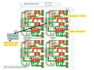
V Input. Kelvin Monitor Points. V Output. Input power +12 volts. Cable. Output / Test Load. Carrier Board. Plug In Card. ASIC Chips Load Keep Short Leads. Yale University October 20, 2009. Relay Current Out Vout/ Load Current IN Voltage IN. 0.5 Ohms. +. Input Power. -.

V Input
E N D
Presentation Transcript
V Input Kelvin Monitor Points V Output Input power +12 volts Cable Output / Test Load Carrier Board Plug In Card ASIC Chips Load Keep Short Leads Yale University October 20, 2009
Relay Current Out Vout/ Load Current IN Voltage IN 0.5 Ohms + Input Power - 0.05 Ohms + Output Power - To Keithley Instruments 2701 Scanning Voltmeterwith 7706 Card 104 A Board: Channels 101 -104 B Board: Channels 105 - 108 C Board: Channels 109 - 112 D Board: Channels 113 - 116 121 103 102 101 CHANNEL Numbers DAC: 123, 124 DIO : 121,122 Power Cable Colors Can Add Extender Cable Red R Orange BK/O Molex 9 pin Female Molex 9 pin Male Black Blue Yellow 5 ft Length 8 Fly Wires Solder to Eval Board Blue/Y or Black Green DC-DC Evaluation Board Model 250 Yale University May 22, 2008
Power IN Enable / Disable Power Good Out Power Out Kelvin points for Vin & Vout Model 2151_Max8654 Yale University April 09, 2009 Yale University April 09, 2009
Power IN Enable / Disable Power Good Out Power Out Kelvin points for Vin & Vout Model 2151_IR8431 Yale University April 09, 2009
Solenoid Copper Coils PCB embedded Coil
4 Wire Current shunt 4 Wire Current shunt DC-DC Converter Voltage ratio = 8/10 Load: Rated Current or maximum without cooling ~ 1 amp Setup for 4 EVAL Boards Measure Bias Current with Load disconnected Power Supply V out > 5 – 20 Volts ~ 0.5 Amps . VInput 5.5 V max to prevent damage. GND V Output Monitor 2 wire Differential Twisted Pair Preferred V Input Monitor. 2 Wire Differential Agilent 34970A & Multiplexer 33901A to Monitor I & V Buck Regulator Eval Board Size = 3 inch x 3.5 inch Twisted Pair Preferred Solder all wires ???? V Output Monitor 2 wire Differential Load Resistor = 0.3 to 1.5 Ώ 1 to 5 Amps . GND V Output = 1.5 V . Switch on/off V Output Monitor 2 wire Differential Line Drop ~ 0.25 volts @ 6 amps in each Leg ??? Banana Jacks / Solder Wires Satish Dhawan, Yale University DC-DC Regulator Setup for Radiation Exposure April 21. 2008
Control Vin: Negative Side Control Vin: Positive Side Fault Output GND +5 Vcc Datel DTL22A-LC Load GND – Negative Side High – Positive Side 20 amps/100 Watt Electronic Load 2 amps / Volt Trimpot 20 KOhms Set maximum current Helipot 10 KOhms GND Electronic Load 2 amps/ volt May 17, 2008