Download
1 / 21
210 likes | 400 Views
Fast digital signal processing of beam signal at ESRF. E. Plouviez on behalf of : J. Cerray, Georges Gauthier, Gerard Goujon, Jean Marc Koch, Graham Naylor. DSP based: Global feedback Booster tune monitor. FPGA based Injection rate monitor BPM processor: HOM instability detector

E N D
Fast digital signal processing of beam signal at ESRF • E. Plouviez on behalf of : J. Cerray, Georges Gauthier, Gerard Goujon, Jean Marc Koch, Graham Naylor
DSP based: Global feedback Booster tune monitor FPGA based Injection rate monitor BPM processor: HOM instability detector Multibunch feedback Fast digital signal processing of beam signals at ESRF • DDC based Graychip 4016 DDC: SR tune monitor • Fast digitizer based: Frequency mapping
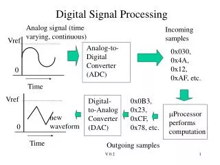
Fast digital signal processing of beam signal at ESRF • DSP: continuous deterministic process, large amount of data processed at audio frequency rate • FPGA: continuous process, data processed at video to IF frequency rate => feedback, monitoring • DDC: frequency selective detection with flexible tuning • Fast digitizer: fast acquisition at video to IF frequency rate, slow but flexible processing
DSP pros and con Pros: • Floating point calculation • Powerful processed data handling, with a proper OS • C programming • Fully deterministic Con: • Assembly math routine library mandatory => code not easily reusable on another DSP! • Fast data input and output bottleneck
upgraded Global feedback C60 Floating point DSP BPMs: (2 BPMs spaced by 5m) correctors: Front end DSP: 32BPMs 24 correctors vertical and horizontal correction C40 links C40 ports taxi bus interface
FPGA beam signal processor Processed data output ADC inputs (AD9226) Xilinx FPGA 352,2 MHz / 10 MHz BW Band pass filter 75,53 MHz / 30 MHz BW Band pass filter Beam signal DAC OUTPUT FPGA 45.44 MHz clock input Mixer oscillator 278.35 MHz ESRF developed CUB board RF mixer local oscillator and FPGA clock generation FPGA clock and IF frequencies choice results in a synchronous I/Q sampling of the beam signal: Amplitude detection => position Phase detection: longitudinal signal 352.2 MHz RF clock
CUB board layout ADC/DAC mezzanine cPCI ESRF developed board: Virtex 1 processor Mezzanine: 4 X 12 bits/ 65 Msps ADC 1 X 12 bits/ 65 Msps DAC Linux device server
FPGA programming MATLAB GUI CubDS server
HOM longitudinal instabilities detection(RF group project) • 500 MHz and 900 MHz RF cavities HOM drive longitudinal instabilities • Beam signals around 150 MHz: 3 X 352,2 MHz- 900 MHz 500 MHz- 352.2 MHz HOM instabilities show on the beam signal as side bands of the revolution frequencies harmonic shifted by the synchrotron frequency: N X 355 KHz +/- 1.8 KHz
HOM longitudinal instabilities detection ESRF developed CUB boards used as DDC to scan the beam and cavity signals to find which cell of a RF cavity drives the instability
Longitudinal feedback • At least 20MHz BW and maybe 180MHz BW (bunch by bunch) feedback: FPGA is the obvious candidate for the signal processing
14 bits ADC and DDC board Spectrum analysis and display (DS + LabView) D RF combiner 72.7 MHz / 10 MHz BW Band pass filter D output RF transfo RF transfo BPM pick up 278.5 MHz oscillator RF transfo RF transfo Tune monitor upgrade Transtech cPCI DDC board Signal preprocessing using a digital down converter board =>large data compression Tune obtained by FFT Beam excitation by noise or small kicks
Frequency map • Many tune measurements after vertical and horizontal transverse kicks of every amplitudes combinations
BPM pick up LPF LPF LPF mapping BPM set up Low b Z.I signal S/D RF combiner D V output ADAS 12 bits 22Msps ADC boars 4 inputs cPCI board: 1000 turns memory depth\ resolution: 2.5mm/turn D H output Resonant RF matching circuits tuned at 352.2 MHz high b X.I signal 352.2 MHz RF clock I signal S output Cell 4-3 BPM bH= 2.9m => DH max= 5.5mm V shaker signal Kicker trig signal bV=35m => DVmax=10mm 64 X frev clock signal
Transverse phase space study at large oscillation amplitude • Will be used to study the non linearity of the beam transverse oscillation at high amplitude